Skip to content

Subject Interface Amplifiers

The Subject Interface Module (SIM) is the control object for the SI2, SI4, and SI8 devices. It connects to a DSP-M or optical QDSP card in your RZ processor. The Subject Interface is configurable with stimulator cards (IZV), analog amplifier cards (PZA), or digital headstage interface cards (PZD). Because of the diversity in functionality of this device, each card type has its own "Sub-HAL" object within Synapse that is used to configure those cards. The acquisition and stimulation all happen within the Sub-HALs, which are all independent objects in the Processing Tree.

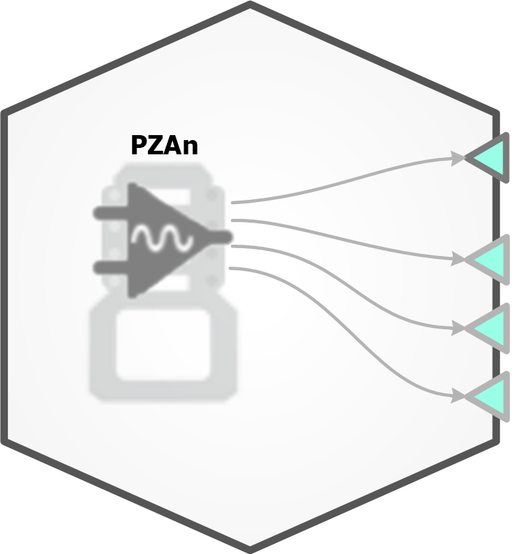
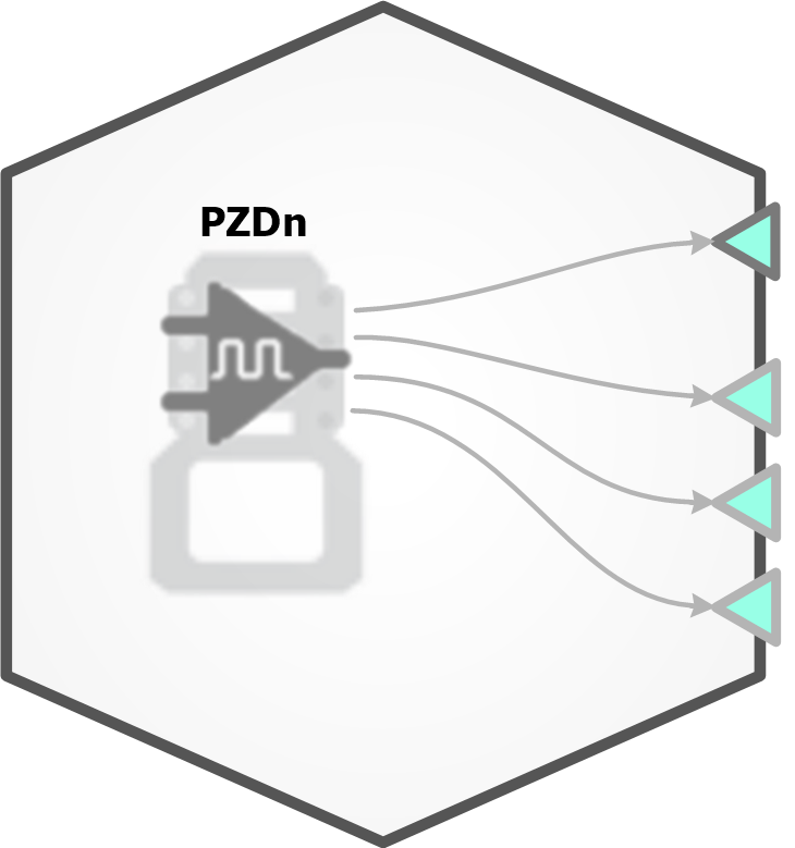
PZA Analog Amplifier & PZD Digital Headstage Interface

The PZA & PZD can split the available boards into sub-amps which are completely isolated from one another.
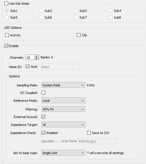
PZA & PZD Options

PZA Analog Options and PZD Digital Options.


Option Description
Use Sub Amps Divide the input channels into "logical amplifiers" that can record different types of signals, at different rates and referencing modes with independent grounds. All of the below configuration options apply only to the selected sub amp.
Boards Specify the number of boards to include in this sub-amp. Selectable values are limited by the Rig configuration.
Channels The channel count must be at least four and must be a multiple of 2. The corresponding physical banks on the SI are displayed to the right.
In Differential Reference Mode set the total electrode count here. The channels from the PZA sub-amp are mapped for you to remove duplicates on the output link.
Name ID Choose the name for this sub amp data source that will be visible to other gizmos
LED Activity Tell the PZA whether to flash the green activity LEDs on its front panel when activity is detected
LED Clipping Tell the PZA whether to flash the red clipping LEDs when the signal is close to saturating the amplifier
Sampling Rate Set the Sampling Rate to match the desired frequency band of your incoming signals (or leave at 'System Rate' if you are unsure). By default, the sampling rate matches that of the RZ.
DC Coupled Remove the 0.4 Hz high pass filter on the input signals and record DC potentials.
Reference Mode Select the mode from the drop-down menu.
Local - each bank of 16 uses its own reference (pin 5 on the DB26).
Shared - all channels in sub-amp share the same reference (pin 5 of first bank in sub-amp).
None - the ground connection is used as the reference.
Differential - each even channel acts as a reference for the odd channel before it. Note: the output channels will be mapped for you to remove duplicate channels.
Filtering Set the anti-aliasing low pass filter cutoff as a percentage of the sampling rate
External Ground Connect this sub-amp ground to the external ground plug on the physical SIM device.
Caution: When using multiple sub-amps make sure they aren't all sharing the External Ground connection or else they won't be isolated!
Impedance Check Enable run-time impedance check
Save to CSV Log impedance values into CSV file stored within the block folder whenever an impedance check runs
Set to base type If you are unsure, use Set to Base Type to configure the amp with default settings based on common signal types
Option Description
Use Sub Amps Divide the input channels into "logical amplifiers" that can record different types of signals, at different rates and referencing modes with independent grounds. All of the below configuration options apply only to the selected sub amp.
Boards Specify the number of boards to include in this sub-amp. Selectable values are limited by the Rig configuration.
Channels The channel count must be at least four and must be a multiple of 2. The corresponding physical banks on the SI are displayed to the right.
Click the Refresh button to automatically detect the connected headstage count (your RZ hardware must be turned on and connected for this to work).
AC Coupled Apply an additional 0.4 Hz high pass filter to the incoming signals.
Name ID Choose the name for this sub amp data source that will be visible to other gizmos
Fast Access Select this option to read the data as 16-bit to reduce cycle usage on the DSP. Required for acquiring 256 channels of digital headstage inputs.
Headstage Detect Tell the PZD whether to indicate the headstage channel count via the front panel LEDs
Sampling Rate Set the Sampling Rate to match the desired frequency band of your incoming signals (or leave at 'System Rate' if you are unsure). By default, the sampling rate matches that of the RZ.
Low Pass Filter Select a cutoff frequency for a lowpass filter that is implemented on the digital headstage. Set to 'Auto' to match it to the PZD sub-amp sampling rate. See table below.
Use DSP Filter Add an additional lowpass digital filter implemented on the RZ, set to the same frequency as the Low Pass Filter setting above, to remove high frequency digital noise from the incoming signal that was added by the digitizing chip
High Pass Filter Select a cutoff frequency for a highpass filter that is implemented on the digital headstage
External Ground Connect this sub-amp ground to the external ground plug on the physical SIM device.
Caution: When using multiple sub-amps make sure they aren't all sharing the External Ground connection or else they won't be isolated!
Impedance Target Use to intelligently control the impedance checking circuit on the headstage based on your target impedance
Impedance Check Enable run-time impedance check
Save to CSV Log impedance values into CSV file stored within the block folder whenever an impedance check runs

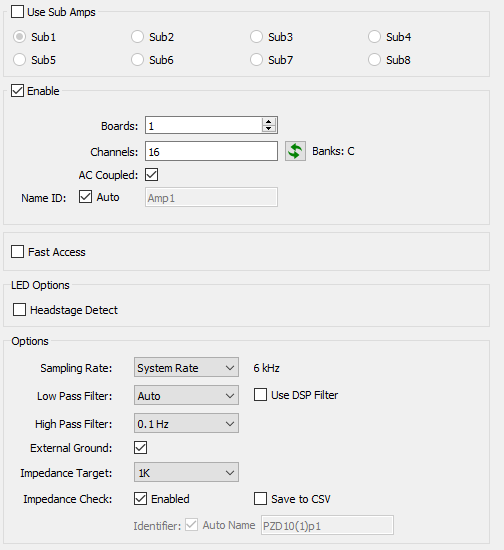
'Auto' low pass filter settings for different sub amp sampling rates

Sampling Rate LP Auto Filter
750 Hz 300 Hz
1.5 kHz 750 Hz
3 kHz 1.5 kHz
6 kHz 3 kHz
12 kHz 5 kHz
25 kHz 10 kHz

See the SIM section of the System 3 Manual for more information about configuring and using the PZA amplifier and PZD interface.

Runtime Interface

When Impedance Check is checked, a user interface appears at runtime.

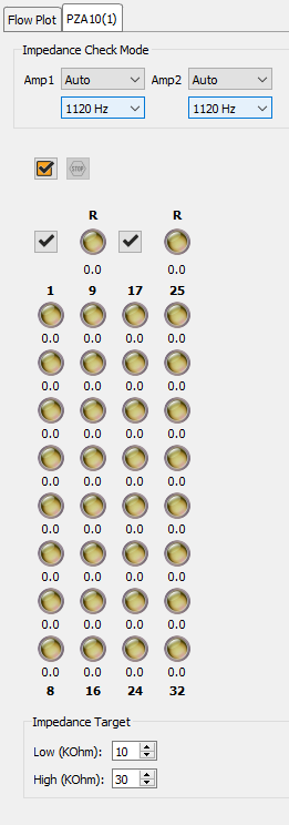
The PZA/PZD Tab provides an interface for impedance checking on all channels. The display represents the stimulation channels divided into banks of eight channels, broken up by sub-amplifier.

The dropdowns at the top define which type of inputs to check and the probe frequency. If a reference electrode is used in the PZA subamp configuration, an LED for the reference is shown with that subamp and it is an available test option. If there are more than one type of input, 'Auto' loops through all of them during the impedance check.

Running the Impedance Check

Run an impedance check on this sub-amp. The PZA/PZD enters impedance check mode and the values are displayed on the interface.

Check All. Run an impedance check on all sub-amps as described above.

Stop Checking. Stops the impedance checking prematurely.

Results of impedance check are indicated by color: below low impedance threshold (green), above high impedance threshold (red), between low and high impedance thresholds (yellow). The actual impedance values (in kOhm) are displayed beneath each indicator.