RZ and RX Processors
RZ Processor Options
Timing Signals
Before looking at the specific experiment HAL options, it is important to know that whenever an RZ Device is included in your Rig, the following timing signals will be available from the device. They will typically show up as drop down menu options when you are configuring a signal source for a gizmo.
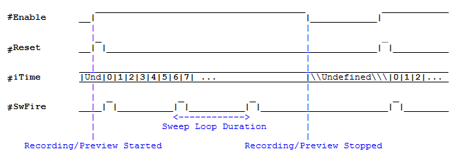 |
| Time Control Waveform Diagram |
RZ Options
Some options may not be available for some RZ devices.
Main Tab
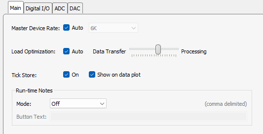 |
| Main RZ Options Tab |
Digital I/O Tab
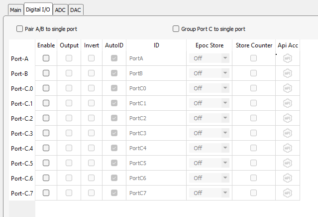 |
| Digital I/O Options Tab |
The RZ has 24 total bits of digital I/O, configured in two bytes (Port-A and Port-B) and eight bits (Port-C). Enable the desired I/O and set the direction with the Output check box. When the Output check box is selected for a given row, a data source must be selected in the ID column. If the Output check box is cleared, that row turns into a data source that can be connected to other gizmos. The name of the data source is set in the ID column.
A counter may also be stored for bits in port C. The counter may be useful for synchronizing to an external camera system.
Select the Pair A/B to single port check box to combine A and B into a single 16-bit integer source or input link.
Select the Group Port C to single port check box to combine the eight bits into a single byte.
Set Epoc Store to 'On Change' to automatically add an Epoc Store for the corresponding byte or 'Full', 'Onset', or 'Offset' for corresponding bit. When this method is used, you don't have to add an Epoch Event Storage gizmo to the processing tree.
ADC Tab
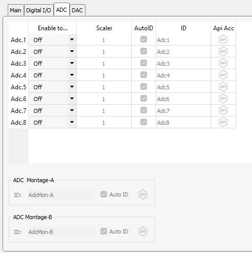 |
| ADC Options Tab (shown for RZ2) |
Analog input channels appear on the ADC tab. Each channel can be used individually as a single channel floating point data source for other gizmos, or can be grouped into one of two montages, which are multi-channel floating point data sources. You can also apply a scale factor to each channel to convert to the correct units.
DAC Tab
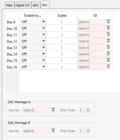 |
| DAC Options Tab (shown for RZ2) |
Analog output channels appear on the DAC tab. For RZ6, the built in attenuators also appear on the DAC tab.
Each channel can be used individually as a single channel floating point data sink, or can be grouped into one of two montages, which are multi-channel floating point data sinks. You can also apply a scale factor to each channel to convert to the correct units before it is sent out of the RZ. A data source for the enabled output channels/montages must be selected.
LUX Tab (RZ10x only)
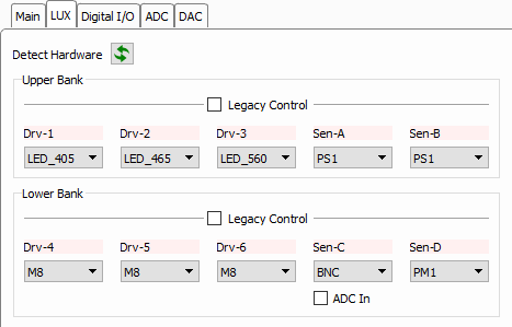 |
| LUX Options Tab |
The RZ10x processors have LUX light drivers, photosensors (PS2), and light power meters (PM1) built into the front panel. They are configurable with slots for up to 3 drivers and 2 sensors/power meters per bank. Each RZ10x has two banks.
With the RZ10x powered on, click 'Detect Hardware' to automatically read the LUX component configuration into Synapse. This will inform gizmos that communicate with the LUX components, like the Fiber Photometry gizmo, about the components that are available.
Built-in LUX LEDs are named by their nanometer wavelength. To use an external LED, use an M8 connector in the light driver slot instead. To use an external LED driver or generic DAC output, a BNC connector is placed in the light driver slot. The BNC port can be accessible as a standard DAC signal output, available in the DAC tab, by checking the 'DAC Out' checkbox below the driver.
If a BNC port is in a sensor slot, it can be accessible as a standard signal input in the ADC tab by checking the 'ADC In' checkbox below the sensor.
Legacy Control
The Legacy Control option makes the entire LUX bank available on the ADC and DAC tabs as regular gizmos inputs/outputs. Use this if you are driving the LEDs with your own custom stimulus signal and not controlling it with one of the gizmos that are specifically designed to target the LUX banks, e.g. Fiber Photometry.
The LUX LED drivers have three output ranges that are exposed in this mode: 200 mA, 500 mA, and 1000 mA. Choose the option that best suits your target output to get the best resolution.
The output range is relative to a 10 V driving signal, so make sure your control signals are scaled properly to get your desired output. For example, a Pulse Train Generator gizmo outputting a 5 V signal to a LUX driver that is set to 500 mA range will output a 250 mA signal to the LED.
RX Processors
See RZ Processor Options above. There are additional options in the Digital I/O tab to determine which port the front panel lights on the RX display.
Legacy Mode
Legacy mode can be used to directly load experiment circuit files (*.rcx) to System 3 processors. This feature allows customers who are transitioning from OpenEx or user-developed TDT applications to port existing experiments directly into Synapse.
The RP2.1, RA16, and RX7 can only be used in legacy mode. Other processors can be switched into legacy mode in the Rig Editor.
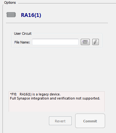 |
| Legacy Mode Device Options |
The illustration above shows the legacy device options for the RA16 Medusa Base Station. The Options are the same for legacy mode, regardless of the device.
Note
Parameter tags in the legacy *.rcx file can be accessed using SynapseAPI.
You can also use gizmoControl macros within Legacy HALs to add widgets to the user interface.
Any storage macros in the legacy circuit will also plot on the Flow Plot.
Options
File Name Enter the path and file name of the circuit to load.
Select Circuit File button Launches an Open window. Select the desired file.
Edit Circuit in RPvdsEx button Launches RPvdsEx. Edit or create a circuit file.