Mapper
Common Use Cases

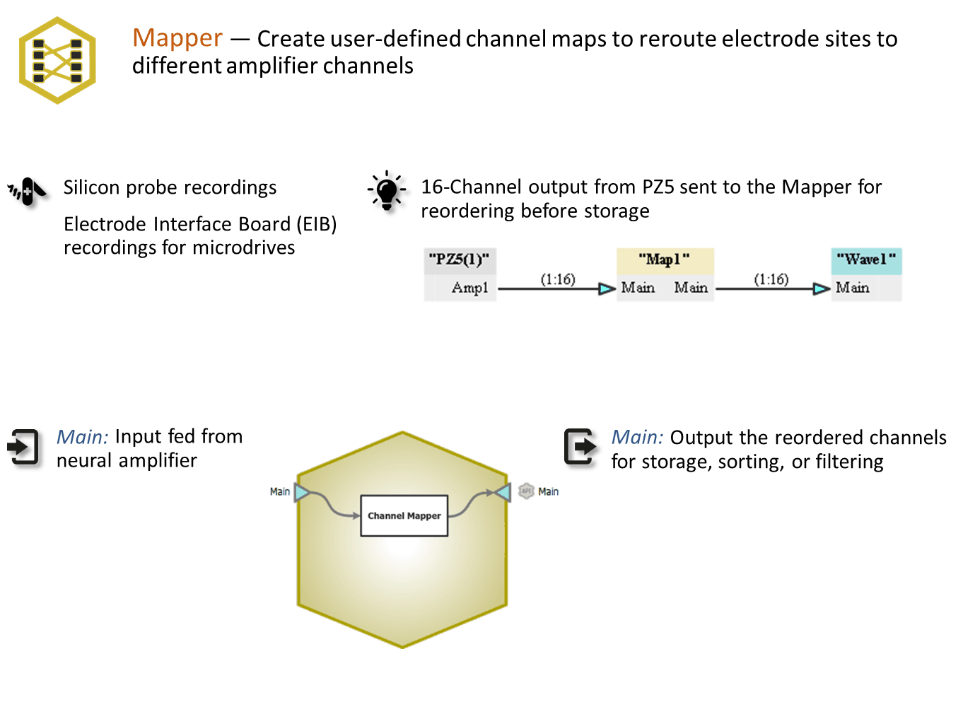
Create user-defined channel maps to reroute electrode sites to different amplifier channels. Use this when you want to create ordered spatial maps with unordered electrode sites.
Gizmo Help Slides
Reference
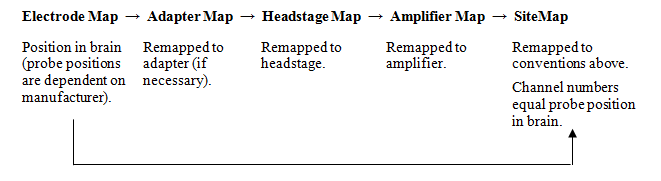
Mapper provides a simplified interface for remapping recording channels. It takes in multi-channel signals then remaps or reorganizes the channel order for your system. You select your electrodes, headstage, and adapters from lists or edit the map manually for custom system components.
See the full Channel Mapping Guide here.
The Mapper Runtime Interface
Map Tab
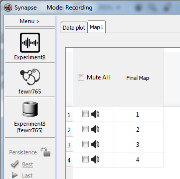
At runtime the channel maps table is displayed for viewing the final map and allowing you to mute noisy channels.
 |
| Runtime Tab |
Mapper Configuration Options
Options Tab
 |
| Mapper Options |
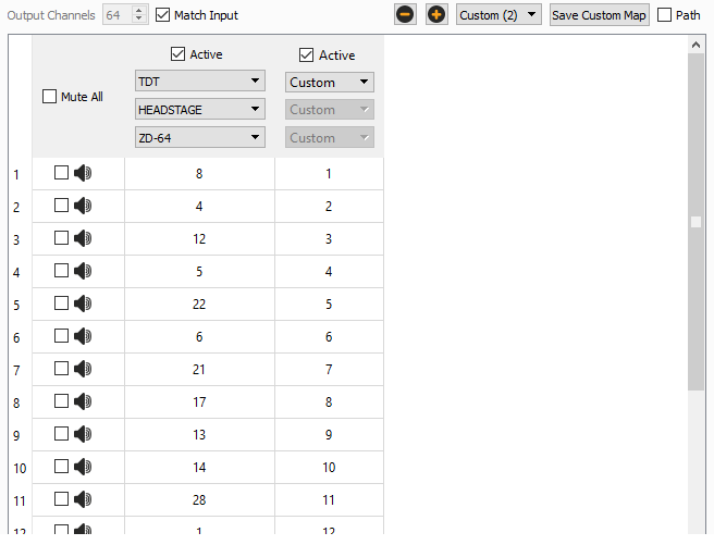
Use the drop-down menu to choose an existing map for your Headstage, Adapter, or Electrode, or create your own Custom map. The default maps are read from a CSV file that installs with Synapse (C:\Synapse\SupportFiles\EAHS.csv). You can add your own maps to this CSV file and they will appear in the drop-down list.
You can enter the channel map manually, or you can copy it from the clipboard by right-clicking on the starting channel that you want to paste the map into.
To only pass a subset of channels through the Mapper gizmo, clear Match Input and change the number of Output Channels.
Click the "-" icon to delete the selected column. Click the "+" icon to add a column to the map. The new column is added to the right of existing columns. All active maps will be applied to the incoming data stream. The Active check box must be selected to allow editing.
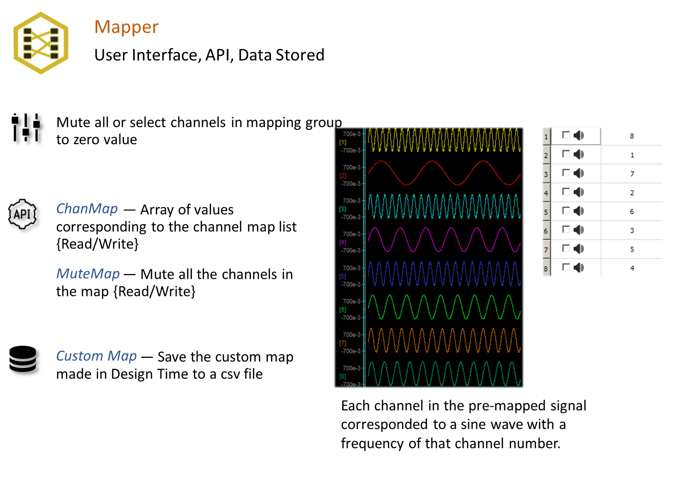
Use the Mute check boxes to set the default mute state of each channel.
Working Directory
 |
| Working Directory Options |
Directly above the mapping interface, you can save the map as a Custom Map or open an existing Custom Map.
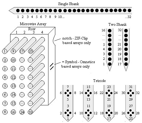
Site Numbering Conventions
Probe sites for shanks and tetrodes are arranged clockwise and in ascending order from tip-to-shank. Omnetics and ZIF-based microwire arrays are arranged in descending order top-to-bottom from left-to-right with the array symbols shown in the diagram below.
 |
| Site Numbering Conventions |