Artifact Blocker
Common Use Cases

Suppress artifacts associated with triggered events. Includes gate timing parameters for control of gate shape. Use this gizmo to remove large artifacts during events like electrical stimulation or motion artifact.
Gizmo Help Slides
Reference
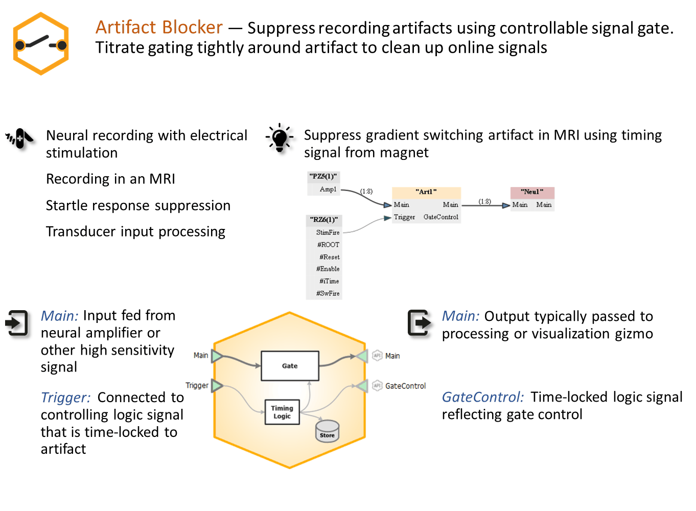
The Artifact Blocker gizmo zeros a signal relative to a trigger, blocking stimulus artifacts in recorded data associated with a triggered event. Timing logic can be stored and/or used as a source for other gizmos.
The Artifact Blocker Runtime Interface
Runtime Plot
If you choose to save gate timing, a plot showing the timing of the gate is added to the runtime window for visualization.
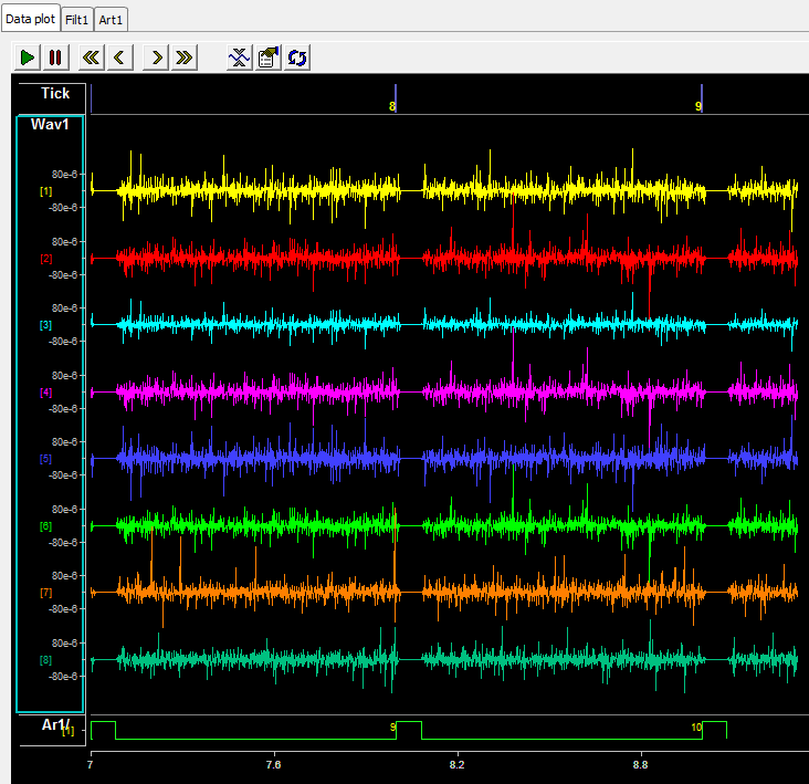 |
| Runtime Plots include Artifact Timing Data |
The main runtime plots show where artifact rejection has been applied to the neural signals.
Artifact Blocker Tab
 |
| Artifact Blocker Runtime Tab |
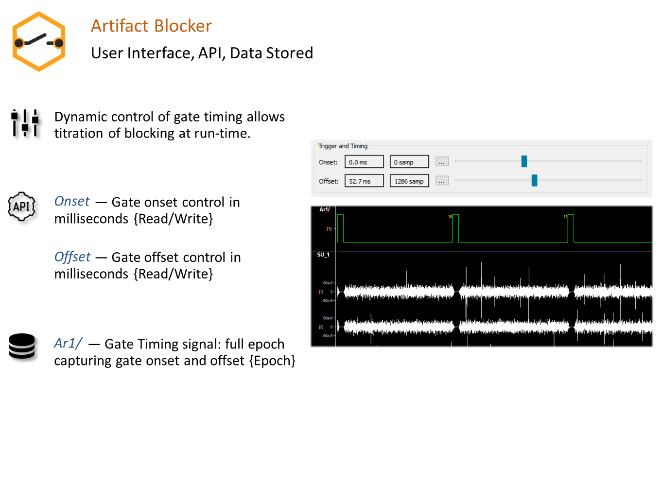
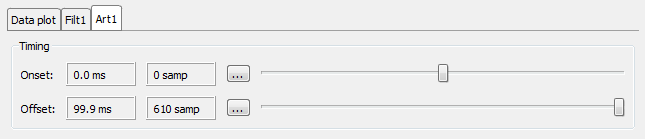
The Artifact Blocker tab has sliders to dynamically adjust the gate onset and offset timing at runtime. If the onset is less than zero, the incoming signal is delayed by that many samples in order to synchronize with the trigger.
Artifact Blocker Configuration Options
 |
| Trigger Options |
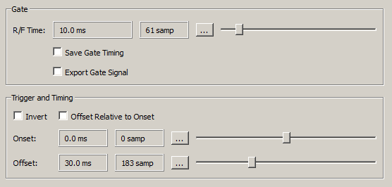
Gate
The artifact blocker uses a cosine-squared gate. The rise/fall time (R/F Time) represents the amount of time it takes to reduce the signal by 90%, and to increase it back to 90% of its final value.
If the specified rise/fall time is less than four samples, a square edge is used which immediately scales the signals by 0 when the trigger onset occurs.
The Save Gate Timing stores the timing signal in the data tank. The Export Gate Signal check box makes the gated timing signal available as an output.
Trigger and Timing
Check the Invert box to reverse the polarity of the trigger input.
Set the default Onset and Offset of the gate relative to the onset of the trigger input. By default the offset is also relative to the trigger, as shown in the gate depiction below.
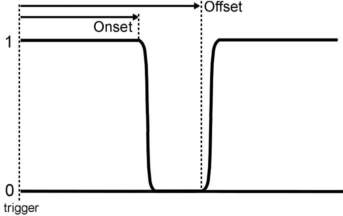 |
| Default Timing Diagram |
If Offset Relative to Onset is selected, the gate signal timing looks like this:
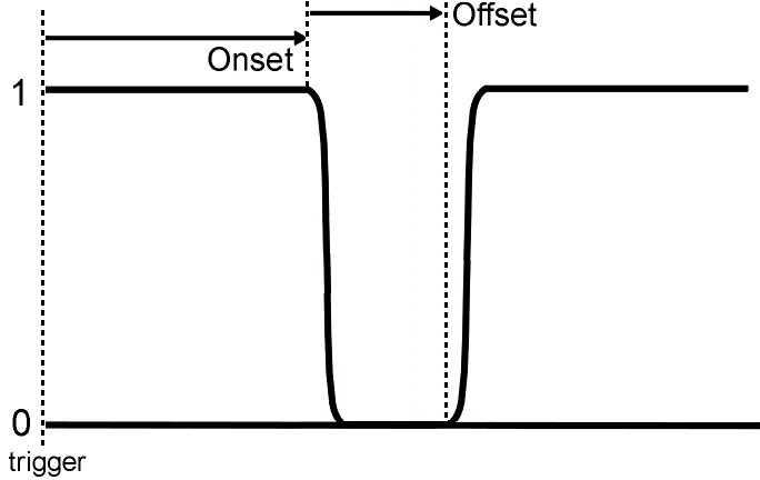 |
| Offset Relative to Onset Timing Diagram |