Pulse Generator
Common Use Cases

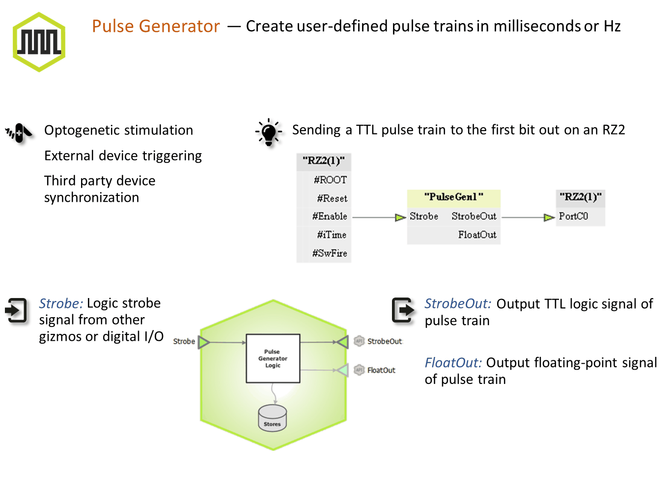
Creates user-defined pulse trains based on milliseconds or Hz. Control duty cycle, period, number of pulses, and trigger pulse trains internally or from other gizmos. Use this gizmo for directly controlling optogenetic stimulation or driving the timing of other connected gizmos or devices.
Gizmo Help Slides
Reference
The Runtime Interface
Runtime Plot
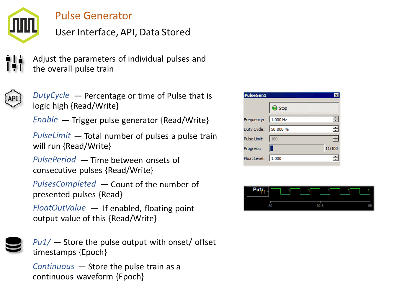
At runtime, the standard Synapse data plot is available to display any stored data. The pulse generator can store its output waveform as onset/offset epoch events and/or as a continuous stream.
Pulse Generator Tab
When Enable Run-time Interface is selected, the user can dynamically control the pulse timing and pulse width, as well as enable/disable pulse output in some modes.
 |
| Pulse Generator Runtime UI |
Pulse Generator Configuration Options
Pulse Shape Tab
 |
| Pulse Shape Tab |
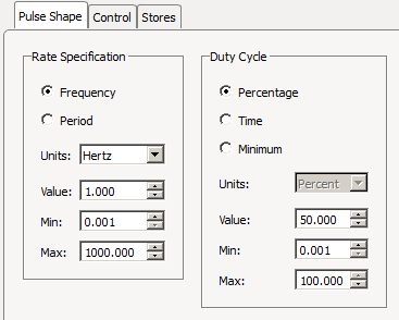
Rate Specification
Choose whether the pulse rate is defined by Frequency or pulse Period.
Frequency defines the onset to onset time in units of hertz, kilohertz, or beats per minute (BPM). Period defines the onset to onset time in minutes, seconds, milliseconds, microseconds, or samples. The default Value as well as bounds on the Min and Max values are set.
Duty Cycle
Choose the pulse high time as either a Percentage of the onset to onset time, or by a fixed Time duration, in units of minutes, seconds, milliseconds, microseconds, or samples. Select Minimum for single sample pulse width.
Control Tab
 |
| Control Tab |
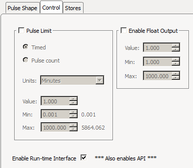
Pulse Limit
Determine when to activate the pulse generator. If this box is unchecked, the pulse generator is active as long as the Enable gizmo input is active or the user has pressed the 'Enable' button on the runtime interface (Run-time Interface must be enabled for the button to appear).
Timed means the pulse generator runs for the specified duration whenever it is triggered.
Pulse Count means the pulse generator runs for the specified number of pulses. It can be stopped by clicking the 'Stop' button on the runtime interface.
Float Value Output
If enabled, adds a secondary floating point gizmo output with the user-defined scale factor.
If Enable Run-time Interface is checked, all Control and Pulse Shape values can be adjusted by the user at run time, subject to the Min/Max bounds specified at design time.
In Timed and Pulse Count modes, the user interface button changes to 'Start/Stop' and only the rising edge of the input is used to trigger the pulse train. The user has the ability to end the pulses before they are finished by disabling the runtime interface button. If the pulse train is initiated by the gizmo input, the button detects this and changes to 'Stop', letting you prematurely halt the pulse train by clicking the button.
Stores Tab
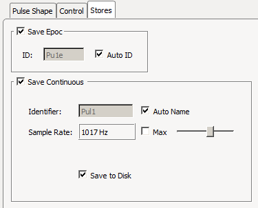 |
| Stores Tab |
Choose what data (if any) to store.
Save Epoc
Store the timestamp of the pulse onset/offset events.
Save Continuous
Saves the pulse train continuously. If the floating point output is enabled, this is the value that is stored.