Subject Interface Stimulation

The Subject Interface Module (SIM) is the control object for the SI2, SI4, and SI8 devices. It connects to a DSP-M or optical QDSP card in your RZ processor. The Subject Interface is configurable with stimulator cards (IZV), analog amplifier cards (PZA), or digital headstage interface cards (PZD). Because of the diversity in functionality of this device, each card type has its own "Sub-HAL" object within Synapse that is used to configure those cards. The acquisition and stimulation all happen within the Sub-HALs, which are all independent objects in the Processing Tree.
Tip
See the Electrical Stimulation Guide for help with experiment design.
IZV Stimulator
The IZV can split the available boards into sub-stimulators which are completely isolated from one another. It is typically controlled by the Electrical Stim Driver gizmo.
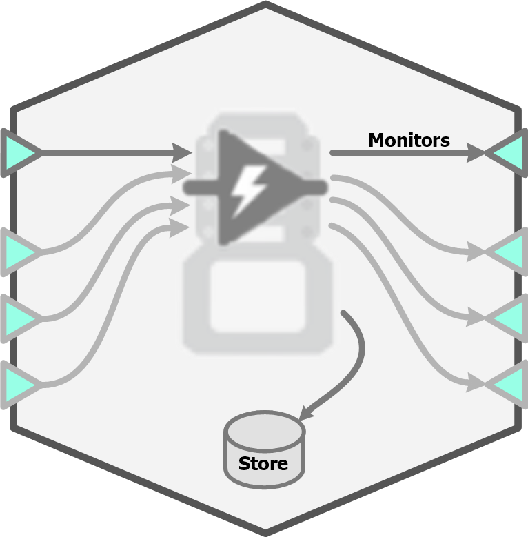 |
| IZV Block Diagram |
IZV Options
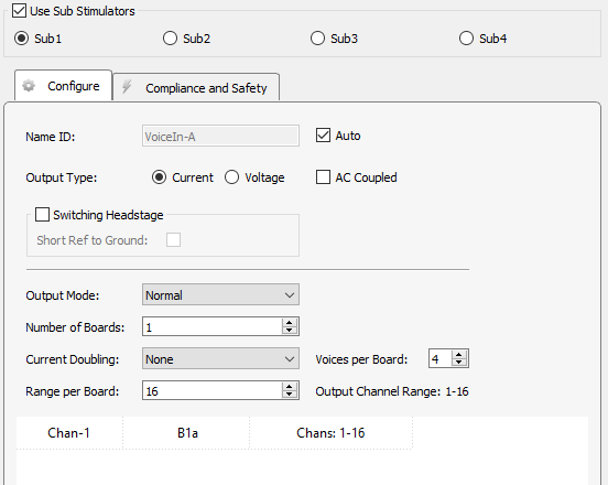 |
| IZV Stimulator Configure Tab Options |
When using Sub Stimulators, each sub-stimulator must be configured independently. Each sub-stimulator has its own multi-channel input signal. For example, the first sub-stimulator uses the gizmo input called "VoiceIn-A", the second sub-stimulator uses "VoiceIn-B" gizmo input, and so on. It is generally expected that this signal comes from an Electrical Stim Driver gizmo so that it has the proper format. The format is a multi-channel signal where the odd channels contain the actual stim waveforms and the even channels contain the target stim channel. For an input that has 4 unique stim signals, it will be an 8-channel signal where channels 1, 3, 5, 7 are the stim signals and channels 2, 4, 6, 8 are the corresponding target stim channels.
Important
The sub stimulators must be ordered from highest to lowest bank count. For example, if you want a 2 bank stimulator and a 4 bank stimulator, then Sub Stimulator 1 should have 4 banks and Sub Stimulator 2 should have 2 banks.
Each physical IZV board has 4 unique hardware voices that can be routed to its 16 output channels.
The data table at the bottom shows the mapping between the gizmo input voices and the physical hardware voices. The first column is the voice of the "VoiceIn" for this sub-stimulator. The middle column is the board number within the sub- stimulator that it uses and the hardware voice on that board it uses (a, b, c, d). The last column is the range of channel numbers that the VoiceIn stim channels should address.
Check the Switching Headstage option only if you are using a ZC-SW switching headstage. If the electrode has a reference site, you may want to short reference to ground in the headstage to help with stimulation artifacts. See Using a Switching Headstage for more information.
Caution
The switching headstage only supports up to ±15 V per channel and can NOT be used in Serial Output Mode.
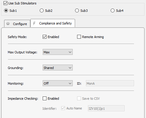 |
| IZV Stimulator Compliance and Safety Tab Options |
See the SIM section of the System 3 Manual for more information about configuring and using the IZV interface.
Runtime Interface
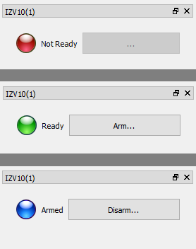 |
| States of the IZV Runtime Interface |
If Safety Mode is enabled on the Safety and Compliance Tab, then an LED will show the state of the compliance monitor. If Remote Arming is disabled, the Arm/Disarm button is shown and the device can be armed when ready.
The system can only Arm if the fiber is connected and a zero current command is sent to the SIM device, so make sure the gizmo controlling stimulation (typically an Electrical Stim Driver) is muted.
Impedance Checking
When Impedance Checking is enabled, a user interface appears at runtime.
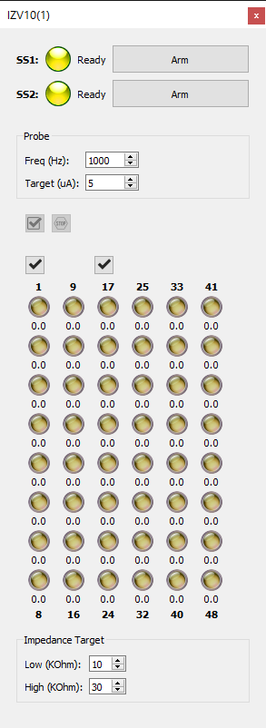 |
| IZV Impedance Checking Interface |
The IZV tab provides an interface for impedance checking on all channels. The display represents the stimulation channels divided into banks of eight channels, broken up by sub-stimulator. Channel numbers are labeled above and below the bank column in the diagram.
In the area above the probe diagram, you can set test signal frequency and amplitude, and define the high and low impedance threshold targets for visualization below the diagram.
Running the Check

Run an impedance check on the selected sub-stimulator. The test signal (sine wave of frequency defined by Freq (Hz) parameter and amplitude defined by Target (uA) parameter) is presented iteratively on each channel in the currently selected sub-stimulator for 500 ms and the impedance is measured.

Check All. Run an impedance check for all channels on all sub-stimulators by cycling through each bank of channels using the test signal as described above.

Stop Checking. Stops the impedance checking prematurely.
Results of impedance check are indicated by color: below low impedance threshold (green), above high impedance threshold (red), between low and high impedance thresholds (yellow). The actual impedance values (in kOhm) are displayed beneath each indicator.
Double-click on an individual LED indicator to run the impedance check on just that channel.