Pulse Train Generator
Common Use Cases

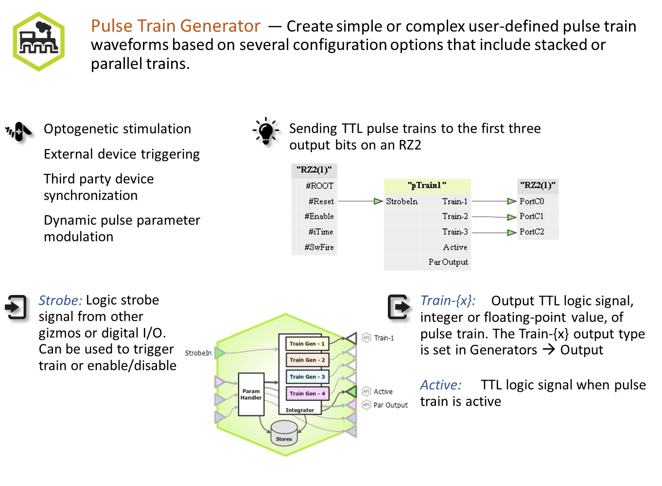
Create simple or complex user-defined pulse train waveforms based on a number of configuration options that include stacked or parallel trains. Control whether trains are strobed or triggered, and define waveform characteristics with a parameter table. Use this gizmo for directly controlling optogenetic stimulation or other connected gizmos or devices. Pulse Train is especially useful when you want to create complex pulse trains where one signal is gating another, or if you want to inform waveform parameters dynamically from other gizmos.
Gizmo Help Slides
Reference
Pulse Train Generator creates a user-defined sequence of pulses. Creates up to 4 different pulse sequences that can be ANDed together.
The Runtime Interface
Runtime Plot
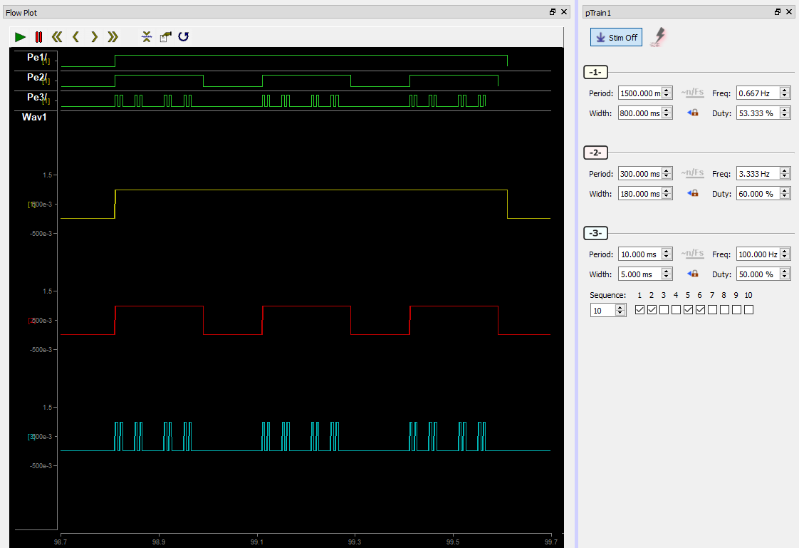
At runtime, the standard Synapse data plot is available to display any stored data. The pulse train generator can store its output waveform as onset/offset epoch events.
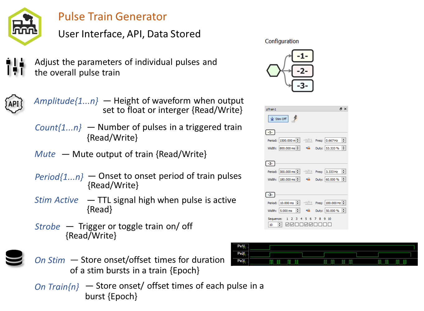
The user can dynamically control any parameter set to Widget mode (the default) at run-time, as well as enable/disable pulse output and Mute the output.
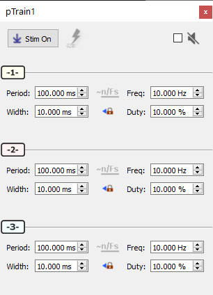 |
| Pulse Train Generator Runtime UI |
Pulse Train Generator Configuration Options
General Tab
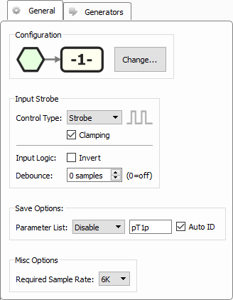
There can be up to 4 trains synchronized together in one Pulse Train Generator gizmo. Use the Change... button to select the configuration. See Generator Order Options below.
Input Strobe
Determines how the master Enable input into the gizmo controls the train presentation.
Control Type Triggered means the trains begin on the rising edge of the gizmo input.
Control Type Strobe means the trains are enabled while the gizmo input is high.
When Control Type is set to Strobe, Clamping means the train is immediately turned off when the gizmo input goes low. If Clamping is disabled, the train pulse is allowed to finish.
Invert Input Logic and Debounce are typically used if the input is coming directly from a digital input on the RZ processor.
Parameter List
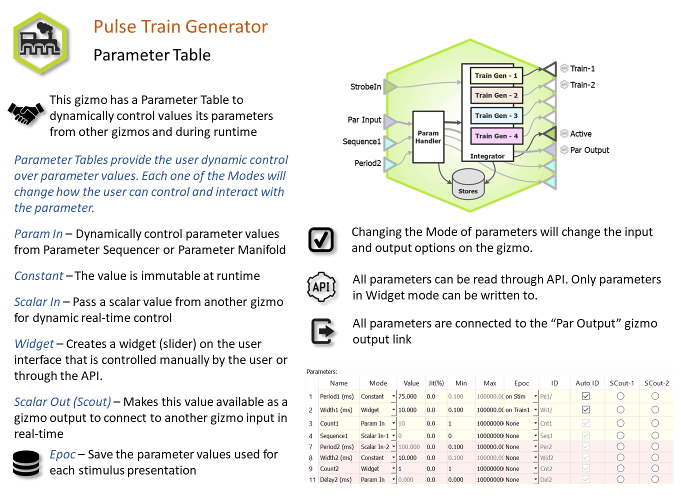
Select whether to store the value of all parameters and on which train onset to store them. This generates a multi-channel list of scalar values. The channels map directly to the rows of the parameters table on the Parameters tab. By default, some parameters are hidden in the table, but values are stored for all parameters.
Auto ID field and check box
A store name is generated automatically. A "/" is appended to the name to indicate when the full epoc is stored (and is not appended when only saving the onset). To use your own store name, clear the Auto ID check box.
Required Sample Rate
The minimum rate required. Synapse looks through the entire experiment and your rig and sets the sample rate according to this and other limiting factors.
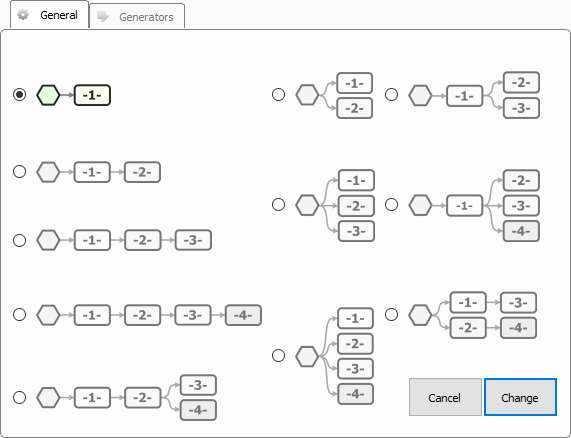
Generator Order Options
 |
| Generator Order Options |
Choose the number of pulse train generators and the control order based on your desired application.
Generators Tab
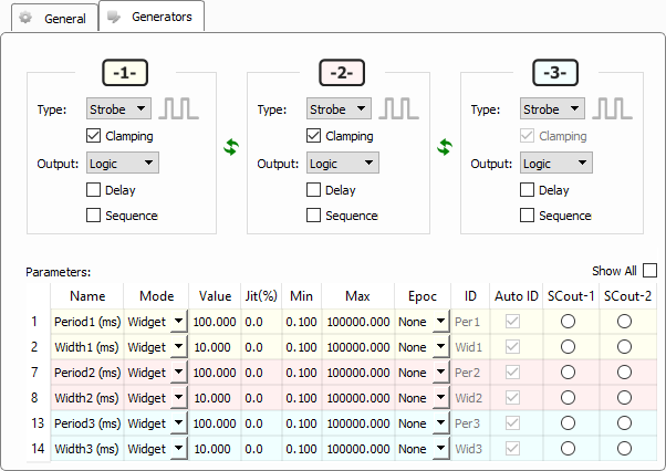
Each parent generator has its own set of parameters for how it controls its child generator.
Type Triggered means the child generators begin on the rising edge of this generator.
Type Strobe means the child generators are enabled while this generator is high.
Type Timer generates a single pulse of the desired Width at the desired Delay.
When Type is set to Strobe or Timer, Clamping means the child generators are immediately turned off when this generator goes low. If Clamping is disabled, the child generators are allowed to finish their current pulse.
Output can be a Logic, Float, or Integer (Float and Integer values are controlled by the Amplitude parameter).
Delay lets you delay the pulse timing with the Delay parameter.
Sequence adds a run-time display that lets you control ordering of presentation. Use this if you want to play a more complex stimulation pattern. See Runtime Sequencing below.
Period defines the onset to onset time in ms. The default Value as well as bounds on the Min and Max values are set.
Width defines the pulse high time in ms
Parameters can be stored as epoc events on the master train or on individual trains.
Runtime Sequencing
 |
| Runtime Sequencing Example |
In this example, three generators are stacked. Generator 1 is the parent of Generator 2 who's child is Generator 3. For the on duration of a Generator 1 pulse, Generator 2 will pulse with on/off times defined by its period and width. The same is true for Generator 2 and 3. Importantly, the Generator with the largest width and period is at the very top.
Generator 3 uses the Sequence option and only presents on the first, second, fifth, and sixth trigger of its timer.
If using SynapseAPI or Parameter Sequencer to control this playback sequence, the structure of the Sequence{N} parameter is an integer where the upper 16 bits indicate the sequence count (up to maximum 16) and the lower 16 bits are the enable code for each step in the sequence. For example, using SynapseAPI in Matlab:
syn = SynapseAPI();

s = [1, 1, 0, 0, 1, 1, 0, 0, 0, 0]
v = bitshift(length(s), 16)
for i = 1:length(s)
    if (s(i))
        v = bitset(v, i);
    end
end

syn.setParameterValue('pTrain1', 'Sequence3', v);