Electrical Stim Driver
Common Use Cases

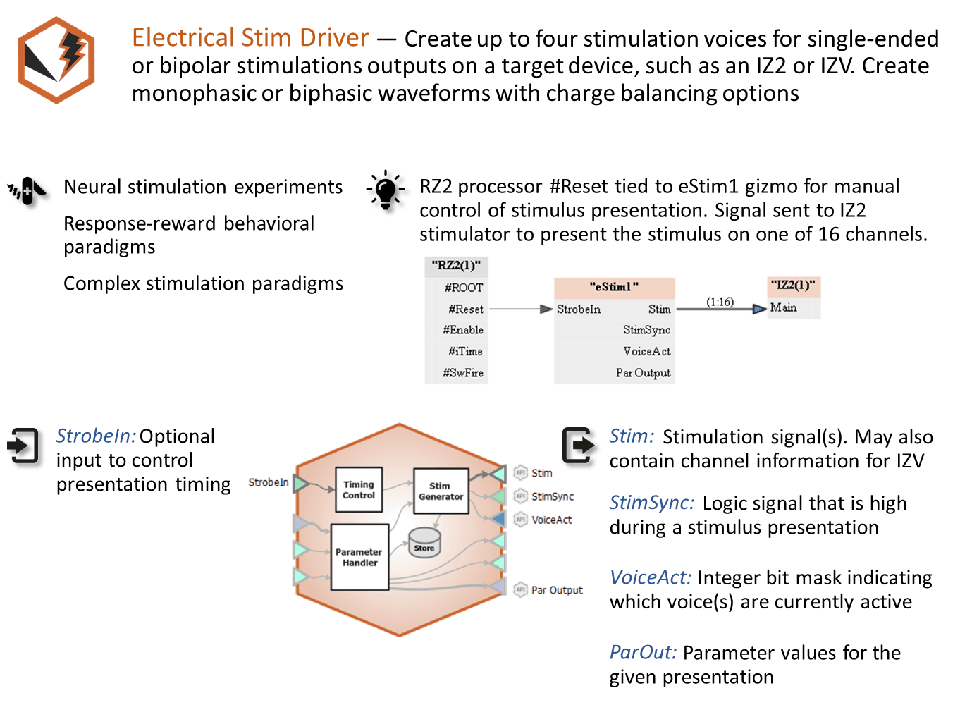
Create up to four stimulation voices for single-ended or bipolar stimulations outputs on a target device, such as an IZ2 or IZV. Create monophasic or biphasic waveforms with charge balancing options. Use this gizmo for design of interesting electrical stimulation waveforms.
Gizmo Help Slides
Reference
The Electrical Stim Driver gizmo configures timing, parameter handling, and electrical stimulation generation with up to four independent stim patterns (voices). It allows dynamic control of stim timings, amplitudes, delays relative to trigger onset, and presentation channels. Output can directly control external IZ2 or IZV (SIM) stimulator device.
Important
For electrical stimulation design with the IZ2, this gizmo replaces the Electrical Stimulation gizmo and Injector gizmo.
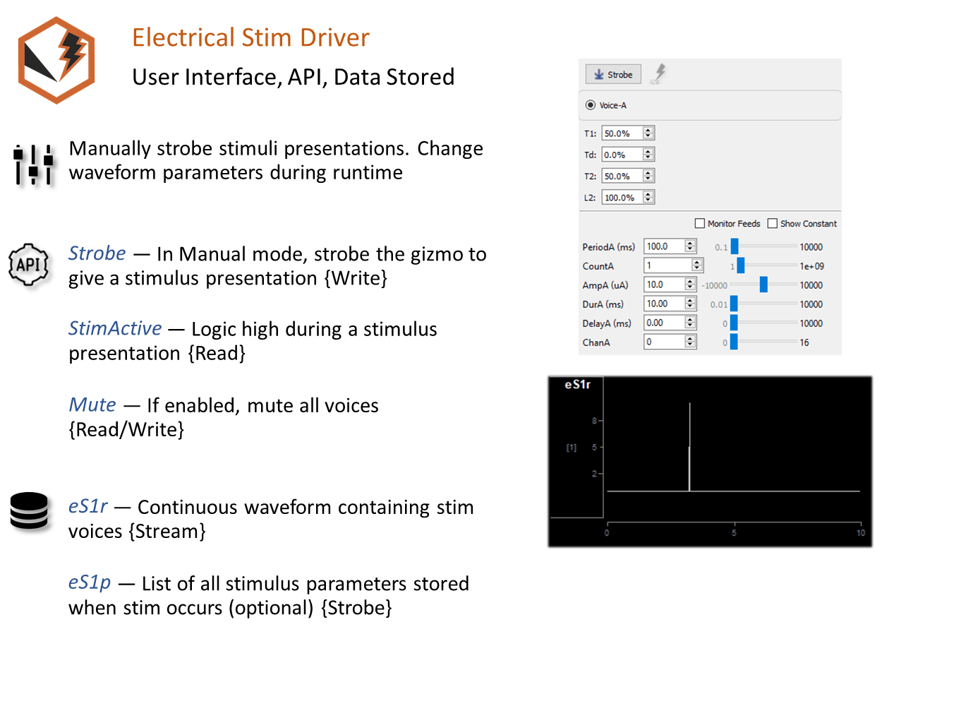
Electrical stimulation waveforms are comprised of square waves that can vary in duration, level, phase, delay, and stim channel. The gizmo provides static or runtime control of stimulus parameters and options to store individual parameters, the parameter list, and raw waveform. Timing pulse can also be output for secondary control or storage.
Electrical Stim Driver Runtime Interface
 |
| Runtime Tabs with Various Stimulus Stores Enabled for Illustration |
The illustration above shows the different ways stimulus information can be stored with the Electrical Stim Driver gizmo. Whichever stores you chose to include will be added to the runtime plot alongside the recording plots. If enabled in the gizmo configuration, a control tab is added at runtime.
Electrical Stim Driver Configuration Options
General Tab
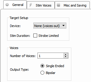 |
| General Tab (Target Device is None) |
Target Device
When set to None (voices out), the Stim output link from the gizmo will contain the voices only.
If Stim Duration is set to Strobe Limited, then the StrobeIn input to the gizmo controls the number of presentations. When triggered, stim presentations continue until the Count* parameter is reached or the StrobeIn input goes low, whichever happens first.
Bipolar mode adds inverted versions of the configured voices to the output signal.
The Electrical Stim Driver will typically be used to control an IZ2/IZ2M or IZV (SIM) stimulator.
When set to IZ2 or IZV10, choose the total number of stim channels on your IZ.
Choose the number of unique stim waveforms (Voices) to present (up to 4). If Bipolar is enabled, you can have up to 2 independent patterns and their inverted waveform on the paired channel.
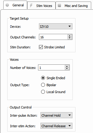
Local Ground mode creates a paired channel for each voice that is shorted to the sub-amp ground to make that paired channel the return path.
You can control the behavior of the IZV channels between individual pulses in a train ('Inter-pulse Action') and between each burst ('Inter-stim Action').
Channel Hold keeps the stim voice connected to the output channel and set to zero
Channel Release open circuits the channel.
Discharge activates a ground clamp (10 kOhm resistor to ground) passive discharge on the stim voice between presentations.
Ground shorts the channel to ground between presentations.
By default, the IZV channels will be open circuit (Channel Release) in between bursts and set to zero current in between pulses in each burst (Channel Hold).
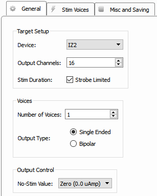
The No-Stim Value option tells the IZ2 channels that aren't actively stimulating how to behave. Zero (0.0 uAmp) sets the control signal to 0 but keeps the channel connected to the stimulator. Open Relay open circuits the channel completely (recommended). Ground shorts the control channel to ground (Note: the Ground option is not compatible with IZ2M or IZ2MH devices).
Stim Voices Tab
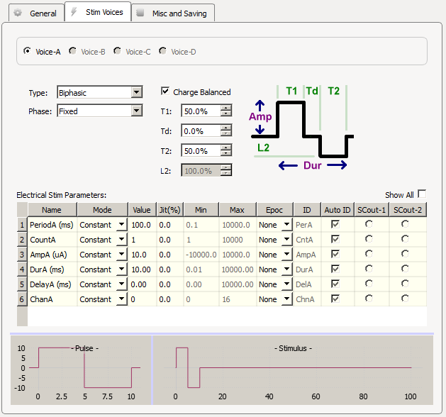 |
| Stim Voices Tab |
Design the waveform shape of each voice. For Monophasic waveforms, the amplitude and duration are controlled by the Amp and Dur parameters.
Biphasic waveform parameters are based on percentage calculations of the Amp and Dur parameters. T1 and T2 are the durations of the phases, with Td the time in between the phases. L2 is the inverted level of the second phase as a percentage of Amp. Check the Charge Balanced box to automatically compute L2 so the total current delivered is zero. This minimizes tissue damage and electrode corrosion for electrical stimulation applications.
Phase
By default, the amplitude of the pulse defines the phase of the stimulus. The Phase setting can control whether to keep the phase Fixed, or to apply an alternating phase per Pulse (toggle between 1 and -1 scale factor on each pulse in the train), or per Stim (toggle the scale factor once before the stimulus train begins).
If the Output Type is Bipolar or Local Ground, a second channel appears for each voice to control the paired channel number.
Electrical Stim Parameters
These define the waveform shapes for each boice.
Tip
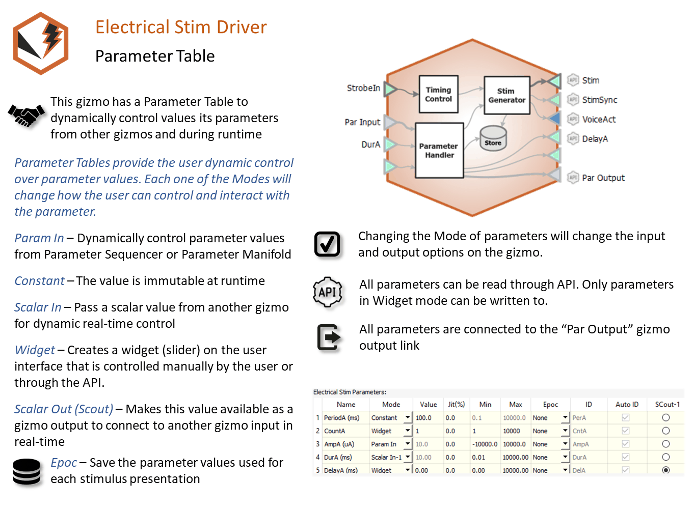
See Using Parameters for more information on controlling parameter tables.
Mode
In the Mode column, you can choose to make an individual parameter Constant, controlled by a runtime Widget, or controlled by a Parameter Input (Param In) or one of two possible Scalar Input lines (Scalar In-1, Scalar In-2).
Value Columns
Enter values in the Value, Jit% (Jitter), Min, and Max columns to set the constant value or to set the initial value when a widget control will be used.
Epoc
In the Epoc column, you can choose to save the individual parameter value on stimulus onset/offset or on individual pulse onset/offset.
ID and Auto ID check box
Synapse automatically generates a store name. TDT recommends using Auto ID to ensure no store names are duplicated. To make your own store names, clear the Auto ID check box.
SCout-1 and SCout-2
Select the radio button in the desired row to feed the parameter to an output line.
Misc and Saving Tab
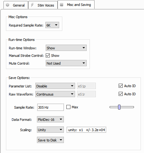 |
| Misc and Saving Tab |
Required Sample Rate
The minimum rate required. Synapse looks through the entire experiment and your rig and sets the sample rate according to this and other limiting factors.
Run-time Window
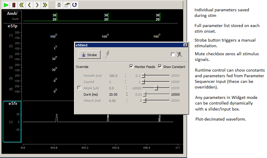
By default a runtime tab is added in preview or record mode. The contents of the tab are defined with configuration options on the General and Parameter options tab. Choose 'Hide' to completely hide this tab. When a stim voice is set to Biphasic, you can also control the T1, Td, T2 parameters at runtime. To hide those controls but show the other controls in the parameter table, choose 'Hide Biphasic Controls'.
Manual Strobe Control check box
When selected a manual strobe control is added to the runtime eStim tab.
Mute Control
Select the default behavior of the runtime mute control. Mute allows you to temporarily zero all stimulus output during runtime. You can choose to hide or show the control and, if show, set the default start state. For controlling an IZ2M/IZ2MH or IZV cards that require arming before you can stimulate, you'll likely want to set this option to Default Muted so that no stimulation comes out when the experiment begins.
Save Options
The options in this area configure stores that can be generated natively within the gizmo.
Parameter List
Select whether to store the value of all parameters, at each stimulus onset. This generates a multi-channel list of scalar values. The channels map directly to the rows of the parameters table on the Stim Voices tab. By default, some parameters are hidden in the table, but values are stored for all parameters.
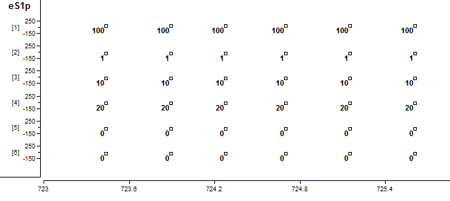 |
| Parameter List Store in the Runtime Plot |
Raw Waveform
Select whether to store a copy of the raw stimulus waveform(s). You can choose to store continuously or only when the stimulus is active. By default the Data Format is set to plot-decimated, which is highly decimated for viewing on your computer monitor. It takes short chunks of points, finds the max and min values, and only keeps those. You can see this effect in the image below. The actual output is a square wave, but during the rising edge it plots the max and min for that chunk of time in the plot decimated view.
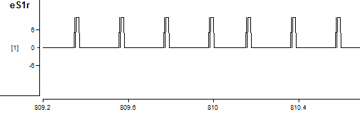 |
| Raw Stimulus Waveform Store in the Runtime Plot |
This is fine for monitoring the peak signal output and requires very low bandwidth. The plot will not contain all of the signal information but will capture the maximum/minimum signal amplitudes. Change the Data Format to Float-32 and increase the Sample Rate if you need a better resolution view.
VoiceAct Output Link
The VoiceAct output is a bit mask where the first bit is the stim trigger, and the next four bits represent whether voices A, B, C, or D respectively are currently stimulating.
PulseAct Output Link
The PulseAct output is a bit mask where the first bit is the stim trigger, and the next four bits represent whether voices A, B, C, or D respectively are sending a non-zero waveform.
In the image below, the four voice output stimulation waveforms are at the top.
- VAct is the VoiceAct output
- Ep1-Ep4 are epocs saved "On Stim" for each voice
- PAct is the PulseAct output
- Ep5-Ep8 are epocs saved "On Pulse" for each voice
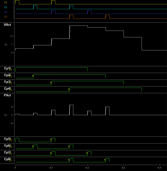 |
| Comparison of VoiceAct and PulseAct output links |