Creating User Gizmos

User gizmos are a class of gizmos which can bring customized processing tasks and user interfaces into Synapse. Any desired processing task that is not already defined in a provided gizmo can be created using user gizmos and then linked into the processing tree, just like any other gizmo.
User gizmo functionality is defined by 'circuits' that are designed in RPvdsEx software. The circuit defines what kind of inputs and outputs the user gizmo accepts and what type of user interface controls will display at designtime and/or runtime to dynamically modify parameters within that gizmo processing task.
Getting Started
Intro
User gizmos are *.rcx files created in RPvdsEx software. To add a user gizmo, add the New User Gizmo in the Processing Tree. The user gizmo interface has two tabs, Circuit and I/O and Control.
 |
| Circuit and I/O Tab |
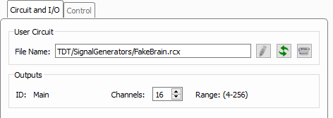
On the Circuit and I/O tab, you can use the first button to the right of the File Name field to browse to an RCX file. Once selected, Synapse parses that file and updates the user interface with any available options, such as user selectable channel counts. If there are any designtime controls specified in the RCX file, they will appear on the Control tab.
The other two buttons on the right allow you to edit the currently selected RCX file in RPvdsEx, and reload the selected RCX file. If you make changes to the RCX file and save it, you must reload it so Synapse can parse it again.
For user gizmos that you want to make readily available in any experiment, place the RCX files in the UserCircuits folder of the Synapse installation directory (typically C:\TDT\Synapse\UserCircuits). Synapse reads this folder and displays the RCX files as gizmos in the Custom category in the Gizmos list so they are always available.
Creating Your Own User Gizmos
User gizmos are designed in RPvdsEx by adding components or macros (pre-made groups of components), linking them together in a logical order, and compiling them as an RCX file.
Prerequisites
This tutorial assumes basic RPvdsEx knowledge of creating processing chains, working with macros and using parameter tags to read/write values dynamically.
Circuit Requirements
The user gizmo macros are available in the Components > Circuit Macros menu in RPvdsEx. There are three macros specific to Synapse user gizmo circuit design that are available in C:\TDT\RPvdsEx\Macros\Synapse: gizmoInput, gizmoOutput, gizmoControl.
Inputs
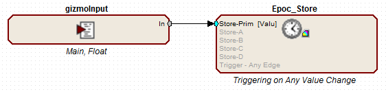
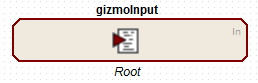
Every user gizmo circuit must have at least one gizmoInput macro. If the user gizmo does not require a data source, for example: if you are designing a signal generator to be used as a data source for other gizmos, set the gizmoInput macro Input Role to 'Root'.
 |
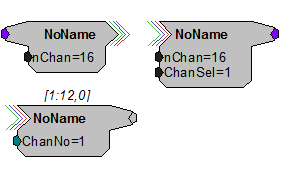
| GizmoInput Macro |
Each user gizmo can receive data from up to four data sources. For each data input into the user gizmo circuit you must add an additional gizmoInput macro and set the Input Role to one of 'Input-1' to 'Input-4'. The inputs must be sequential with no gaps in numbering. If the user gizmo requires at least one data source, you do not need a 'Root' gizmoInput macro in your circuit, 'Input-1' takes its place.
For each input data source you specify the allowed data type and channel count range so the Synapse compiler can properly connect it to other gizmos.
Outputs
A gizmoOutput macro is required if the user gizmo will be a data source for other gizmos. Up to four outputs are allowed in each user gizmo, named 'Output-1' to 'Output-4'. Each output requires its own gizmoOutput macro, where you specify the name, data format and allowed channel count range. The outputs must be sequential with no gaps in numbering.
You also set the output channel dependency. This can be 'Prompt' if the user gizmo is acting as a signal generator, which means the user will select the channel count at designtime, or you can link the channel count to one of the gizmoInput channel counts. For example, a user gizmo that does some custom filtering on a multi-channel signal would likely have an output channel count that matches the input channel count.
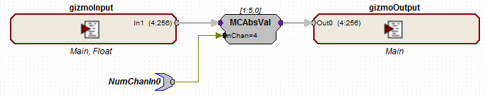
If you need to use the channel counts for the inputs/outputs in the processing chain, use specially named parameter tags. These parameter tags must be named NumChanIn{n} and NumChanOut{n} where n is 0, 1, 2, or 3, one for each of the four possible inputs and four possible outputs. Anything connected to one of these special parameter tags is given the value of the specified channel at compile time.
In the example below, the user gizmo is performing an absolute value operation on a multi-channel floating point data source and making the resulting signal available to other gizmos. It accepts between 4 and 256 floating point channels on the input. Here, the 'nChan' parameter of the MCAbsVal component will be replaced by the number of channels on the input data source when Synapse compiles this circuit into the processing tree. This ensures the MCAbsVal component will always have the correct number of channels.
 |
| Custom Absolute Value Gizmo Circuit |
User Interface Widgets
If there are parameters in the processing chain that you want to control at designtime or runtime, or that you want to display to the user at runtime, you can specify a user interface widget and attach it to a specific parameter tag in your circuit.
Add a gizmoControl macro for any parameter tag that you want to display a user interface widget for. The gizmoControl macro determines whether this tag is read or write, what type of widget to display, when to display the widget (designtime or runtime), and other configuration options.
The parameter tag name must always be prefixed with "ID_". When Synapse compiles the processing tree, "ID" is replaced by the gizmo name. This allows you to use multiple instances of the user gizmo and prevents naming conflicts.
If any user interface widgets are specified to show at designtime, they will appear on the Control tab in Synapse. Any that show at runtime will have their own tab in the runtime interface. The controls will be organized alphabetically by parameter tag name on the runtime screen based on window size.
Removing Unused Components
It is important to keep circuit design in your user gizmos as efficient as possible. If you're unable to us multi-channel components and must instead use an iterate box in your circuit, you can dynamically remove unused components inside iterate loops by naming them "KILL~{x}".
Two-Sample Delays
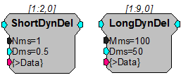
Like all gizmos, user gizmos add a two sample delay to the processing path. This is particularly important to keep in mind for tasks where timing is critical. In cases where you have more than one signal or processing path, RPvdsEx delay components (such as: SampDelay, MCDelay) can be placed in a user gizmo to synchronize the paths.
MATLAB/Python Access
SynapseAPI can also be used to read and write parameter tags in the user gizmo circuit. The parameter tag name must always be prefixed with "ID_" to avoid naming collisions when multiple instances of the same user gizmo are used on the same device.
See the SynapseAPI Manual for more information.
User Gizmo Do's and Don'ts
The following list of RPvdsEx components are not available in user gizmo circuits. Some may have alternatives.
Unsupported RPvdsEx Components


HRTF Support
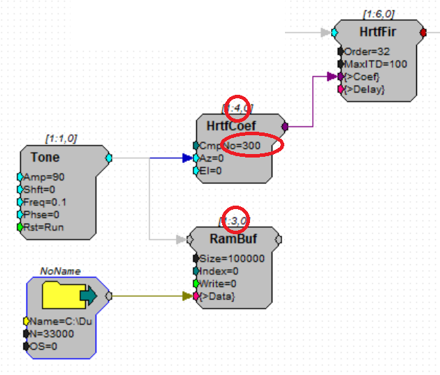
Use a circuit construct like the one shown below to force the compiler to place the RamBuf component just before the HrtfCoef component in the processing order. Verify it is properly ordered by clicking the compile button in RPvdsEx. Then specify a CmpNo = 300 on the HrtfCoef component.
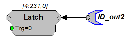
Parameter Tags
Parameter tags must be attached to a port that is typed (float, integer, logic). Do not connect a control tag to a gray non-typed port.
good
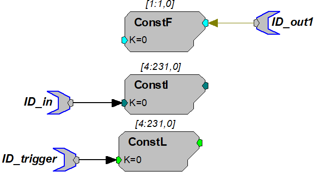
bad
Legacy OpenEx macro support
The standard OpenEx macros can be used in user gizmos. All of the timing structures you need are included in the gizmoInput macro. The SpikePac macros are NOT supported in user gizmo - use their corresponding TDT Gizmo replacements instead.