Using Parameters
A bounded parameter is a named value that controls a parameter in the underlying real-time processing of the gizmo that contains it. The parameter's value can be modified at runtime by the user or by another gizmo. The user sets the allowed minimum and maximum values of each bounded parameter at designtime. These values are enforced whenever the parameter value is modified.
Gizmos that support bounded parameters share a common runtime interface which gives you manual, semi-automated or fully-automated control of the parameters at runtime.
The stimulation gizmos share a common set of bounded parameters with consistent names to define and organize information about the stimulus parameters so that you can easily switch between them. All of the stimulation gizmos and many of the routing gizmos use parameter tables.
Video Demonstrations
Follow along with these videos for a full experiment walkthrough using signals and parameters.
Signals & Parameters Part 1
Signals & Parameters Part 2
Parameters Table
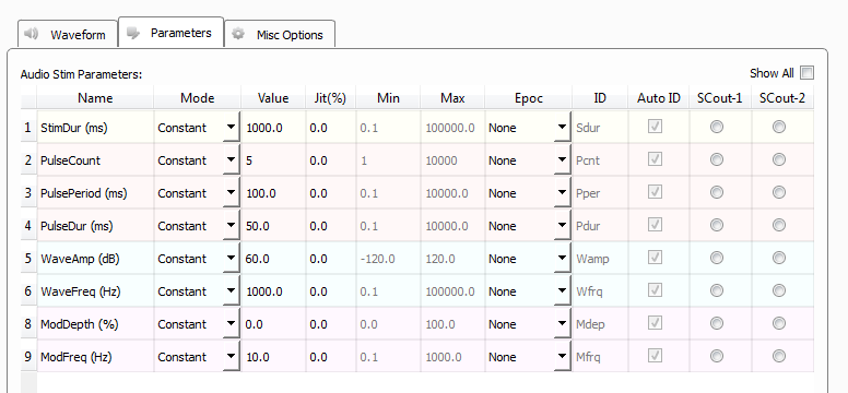
Gizmos that support bounded parameters have a Parameters tab in their designtime interface that contains the parameters table. The parameters table contains all of the possible bounded parameters for that gizmo. The Audio Stimulation gizmo parameter table is shown in the example below.
 |
| Parameters Tab |
This table allows the user to set the parameter source and bounds at designtime, among other things that are discussed below.
Rows are shown or hidden depending on the stimulus type and in response to selections made during configuration, with only relevant parameters shown. Likewise, the columns contain values to further define the parameter and are enabled or disabled (gray) by choices you make during the design process.
Value and Min/Max
Value sets the default value for the parameter when you switch to runtime mode.
All parameters are bounded by their Min and Max values. Whenever possible, narrow the bounds to the most reasonable values for the parameter.
Min and Max set the bounds on any runtime slider widgets and inform any upstream gizmos, such as Parameter Sequencers, about the required values.
Right-click in the Value cell to open a pop-up dialog for easier value entry.
Epoc and ID
In the Epoc column, you can choose to save the individual parameter value on a strobe event or on value change. The options differ depending on the type of gizmo.
Synapse automatically generates a store name. TDT recommends using Auto ID to ensure no store names are duplicated. A "/" is appended to the name to indicate when the full epoc is stored. To make your own store names, clear the Auto ID check box.
Mode
In the Mode column, you can choose to make individual parameters constant, dynamically controlled by a runtime Widget (slider), dynamically controlled by a parameter input (Param In) from a Parameter Sequencer gizmo or Parameter Manifold gizmo, or dynamically controlled by one of two possible single channel gizmo inputs (Scalar In-1, Scalar In-2).
Constant
In constant mode, Value defines the value of the parameter. The value can be seen in the runtime interface, but cannot be changed.
Jit%, or percentage jitter, acts as a randomizer for each presentation. If non-zero, then Min and Max provide the bounds.
Widget
 |
| Widget Run-time Interface |
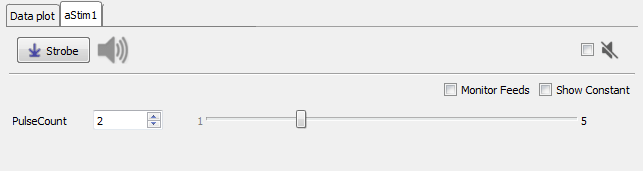
In Widget mode, Value, Jit%, Min, and Max define the reasonable limits for the parameter and set the initial value.
At runtime a interface is added as a tabbed window that includes a value box and slider for the parameter(s) set to Widget in the table. A manual Strobe button presents a single stimulus. A mute button zeros the signal when checked.
Scalar Inputs
Scalar Inputs 1 and 2 provide a gizmo input to control a parameter directly from any other floating point signal within the bounds defined for the parameter
Tip
You must set the parameter up in the table and Commit the change, then update the source for the new input in the block diagram.
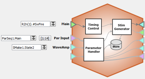 |
| Block Diagram with Several Stimulus Parameter Inputs |
Param In
In Param In mode, the parameter value is read in from another gizmo. Jit% (Jitter), Min, and Max primarily define the reasonable limits for the variable. Param In is intended specifically for use with the Parameter Sequencer gizmo or Parameter Manifold gizmo. You will need to configure the stimulus, and choose the Param In mode before adding the Parameter Sequencer or Parameter Manifold gizmo to the Processing Tree. Once attached to the parent gizmo, the parameters from the stimulus will be automatically added to the parent's parameter table.
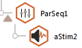 |
| Parameter Sequencer and Audio Stimulation Gizmos |
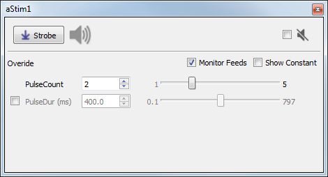
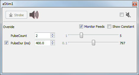
In the example below, Pulse Count is controlled by a widget and PulseDur is controlled by in a parameter input. The Monitor Feeds check box shows the parameter controlled input.
Notice, on the left, only the widget controlled parameter is editable. On the right, The check box in the Override column next to the PulseDur (the Param In controlled) parameter has been selected and is now editable.
This allows you to override the Parameter Sequencer inputs at any time.
 |
| Stimulation Runtime Tab Showing "Monitor Feeds" Enabled |
Scalar Outputs
Use radio buttons in the SCout-1 or SCout-2 columns to select a parameter to output. The output can then feed an input on another gizmo. You must commit the change before the new output line will be enabled and labeled in the block diagram.
User Parameters
User-1 and User-2 are parameters meant for your custom needs. These parameters can be virtually anything you need them to be. For example, they can be useful for defining a stimulus presentation channel controlled by the Sequencer.
To locate these parameters:
-
On the Parameters tab, select the Show all check box and scroll to the end of the list.
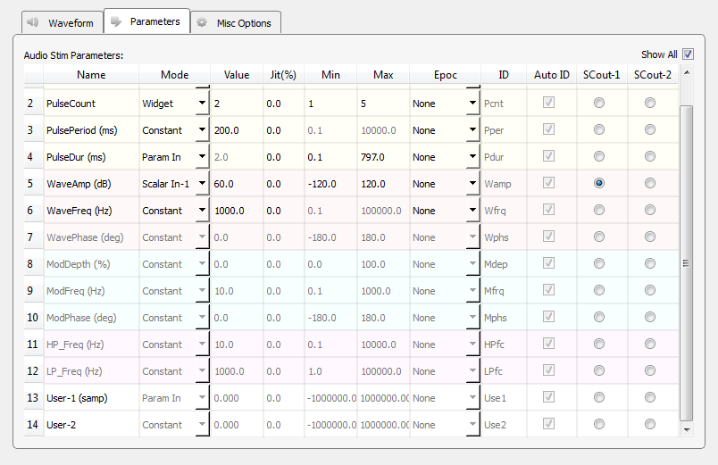
Parameter Table with Show All Selected -
After you locate the User parameters, double-click the name cell to open the Parameter Details dialog box.
Important
You must select the Active check box to enable it.
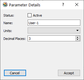
Parameter Details Dialog Box In the dialog, you can define some of the parameter's basic properties. Once the properties are accepted and the parameter is active, you can configure it much like you would any other parameter.
The Parameter Sequencer Gizmo
Stimulus gizmos uses uniform parameter tables to configure the stimulus parameters. Because the tables are structured using consistent parameter structure and naming, you can use a Parameter Sequencer gizmo or Parameter Manifold gizmo to feed values to one or more parameter tables in a systematic way.