Cluster Processing with Synapse
Overview
Cluster Processing is Synapse's solution for research that demands higher channel-count recordings or more processing power. Cluster Processing:
-
Eliminates data bottlenecks
-
Delivers more PC processing power for data visualization
-
Overcomes zBUS bandwidth limitations
-
Enables separation of stimulation and recording components, while remaining synchronized
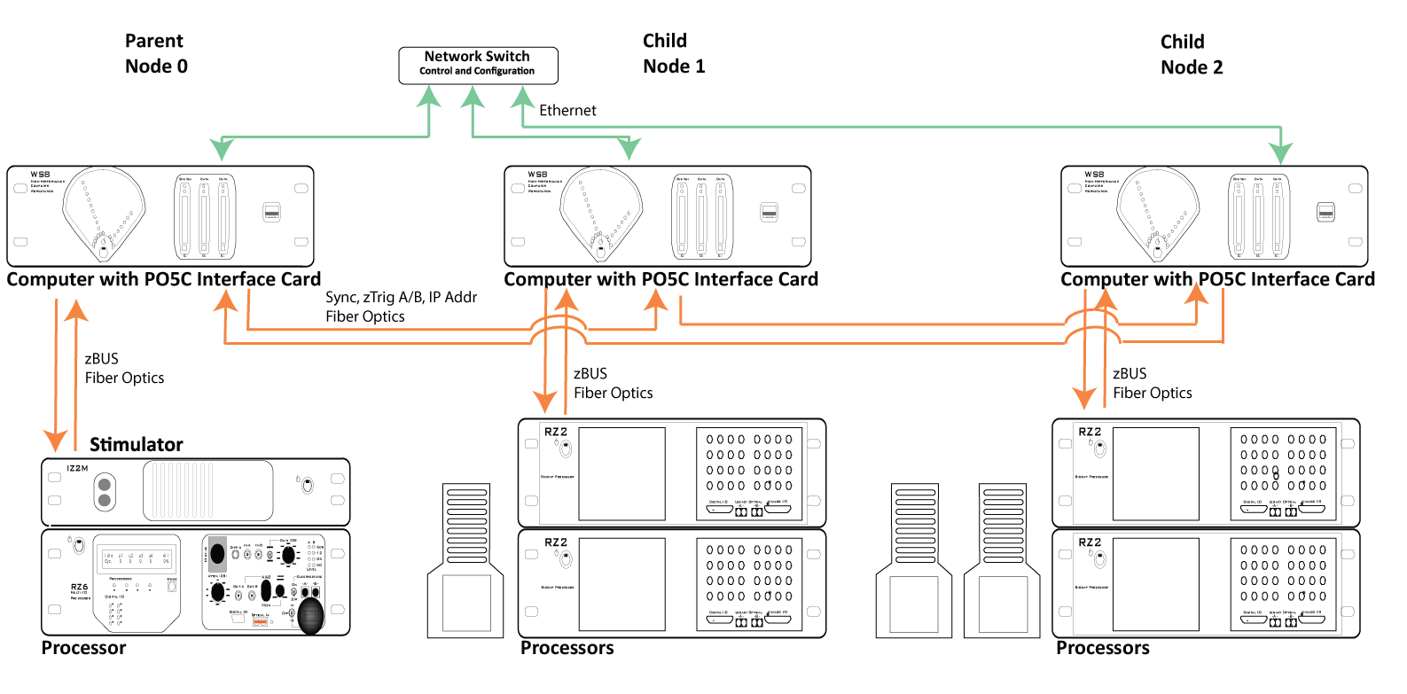
Multiple complete systems, including System 3 hardware and computer, are networked and synched to a single system clock from which acquisition is triggered. This allows a single experiment to be distributed across multiple systems with one system serving as a "parent" node and the other systems as "child" nodes. This is accomplished using PO5c interface cards installed in each system PC. A switch on the card sets the parent/child role for the PC and its related hardware.
The parent node is always node 0. Synapse must be installed and running on all nodes. The PO5c includes a standard zBUS fiber Optic port and a second port that connects the cluster PCs in a "daisy-chain" fashion, delivering clock and trigger signals as well as system IP Address. Once in Cluster mode, The Rig Editor and Processing Tree on the parent computer become tabbed objects. Each tab configures a different node. The operational mode, such as Record or Preview, is controlled on parent node 0 during an experiment.
 |
| Cluster Processing Overview Diagram |
The network connection is used to send experiments to the child nodes and report status to the parent node.
Setting Up Cluster Computing
Installation
Synapse must be installed on each computer that will be used as a node in the cluster.
To launch in Cluster mode, add "/cluster" to the command line path. For example:
C:\TDT\Synapse\Synapse.exe /cluster
PC Requirements
All PCs must have an Ethernet, network connection and a PO5c System 3 interface card installed.
TDT Hardware Requirements
Each node in the system must be a complete system with computer, interface card, and connected RZ processor.
Hardware Configuration
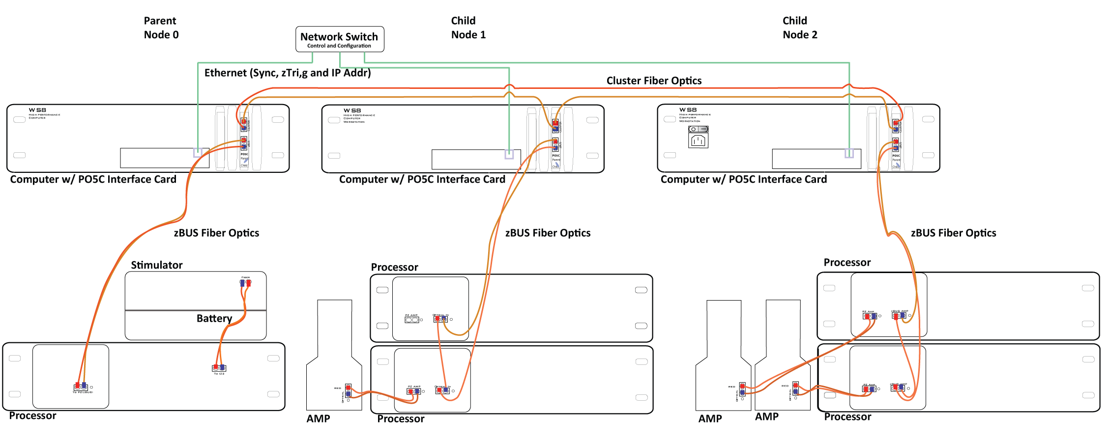
When configuring your hardware, begin by connecting each individual node as you normally would for a single system. See the System 3 Installation Guide for detailed instructions. When the connections within the node are complete, you will connect the nodes together using the CLUSTER fiber optic ports on the PO5c cards as shown in the diagram below.
Connect Node 0 output to Node 1 input and Node 1 output to Node 2 input and so forth and then connect the final node output back to Node 0 input. After all fiber optic connections are complete, connect each node's Ethernet port to a shared network.
 |
| Cluster Computing Hardware Connection Diagram |
Each node's role is determined by the parent/child switch on the PO5c card. The switch settings must match the node's position in the chain with Node 0 being the only Parent.
You can confirm that the cluster is correctly configured using the zBUSmon utility.
To launch the utility:
-
Click the zBUSmon shortcut on the parent desktop.
-
Repeat for each child computer.
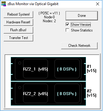 |
| zBUSmon on Parent Node |
Parent Node Interface Display
At the top of zBusMon, find:
- Interface Card and Version
- Node number
- Number of nodes
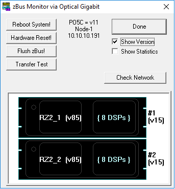 |
| zBUSmon on Child Node |
Child Node Interface Display
At the top of zBusMon, find:
- Interface Card and Version
- Node number
- IP address of Parent (Synapse running on parent node)
The Rig
The Rig Editor is accessed and used much the same in Cluster Mode. If multiple nodes are connected, a tab will be added to the Rig Tree for each node.
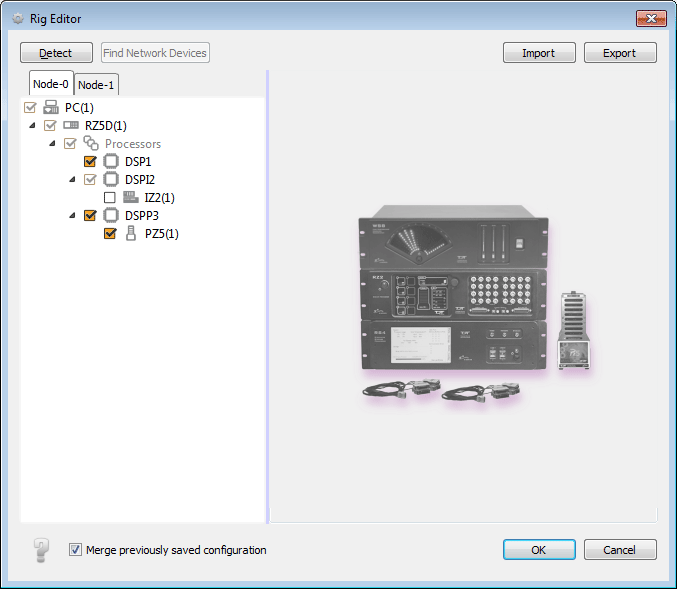 |
| Rig Editor: Cluster Mode, Node 0 |
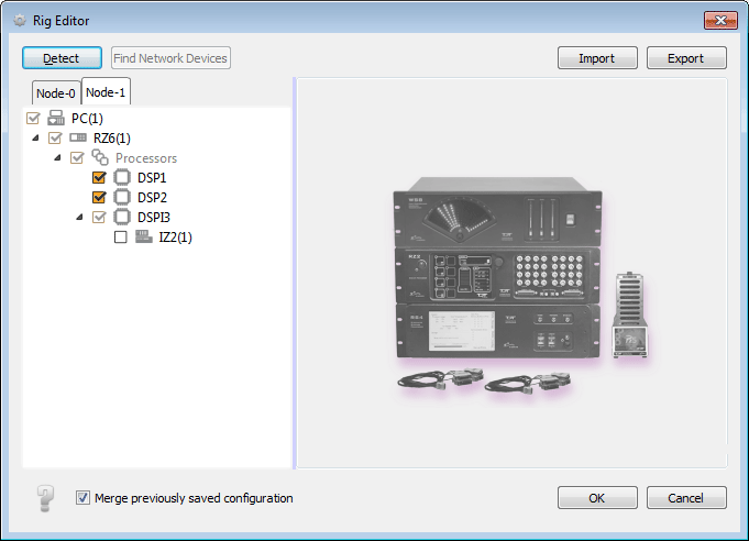 |
| Rig Editor: Cluster Mode, Node 1 |
Processing Tree
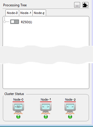 |
| Processing Tree in Cluster Mode |
In Cluster mode, the Processing Tree is comprised of a tab for each node - the computer and connected System 3 devices. The experiment is designed using the node 0 computer. Here, you can see the hardware available in each node and use gizmos to create a processing tree for each node.
At the bottom of the Processing Tree pain, icons are displayed for each node. If a node has been previously defined and is not currently connected, the missing asset is shown in gray and the corresponding tab is disabled. The icon also includes indicators for synchronization and connection status via the orange square pulse.
Every Commit compiles not only the parent experiment but also the child experiments. If that is successful, the child experiments are pushed to the child nodes and imported. The import status from all children is returned to the parent.
Preferences
In Cluster Mode a Cluster Ops tab is added to the Preferences dialog box. On this tab, you can chose to manually set the parent/child roles and the name, IP Addr, and Nic for node 0. You can also set the length of the Mode Change Timeout.
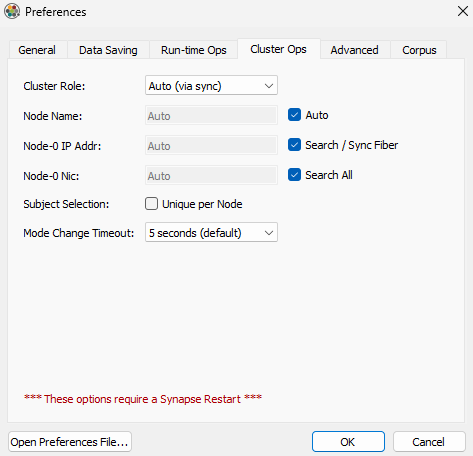 |
| Preferences Dialog, Cluster Ops Tab |
By default, the user, experiment and subject are common across all nodes. The Subject Selection check box allows you to make the subject different for each node. This is particularly useful when running multiple subjects in a single recording session.