Electrical Stimulation

The Electrical Stimulation gizmo configures timing, parameter handling, and
electrical stimulation generation.
Important
The Electrical Stimulation gizmo was replaced by the Electrical Stim Driver gizmo. It is only available if you enable Deprecated gizmo in Menu → Preferences.
Reference
Electrical stimulation waveforms are comprised of square waves that can vary in duration, level, and phase. The overall stimulation duration can be set by a fixed duration, based on a strobe or based on pulse count. The gizmo provides static or runtime control of stimulus parameters and options to store individual parameters, the parameter list, and raw waveform. Timing pulse can also be output for secondary control or storage. Both the stimulus and the inverse of the stimulus are gizmo outputs.
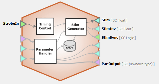 |
| Electrical Stimulation Block Diagram |
Electrical Stimulation Runtime Interface
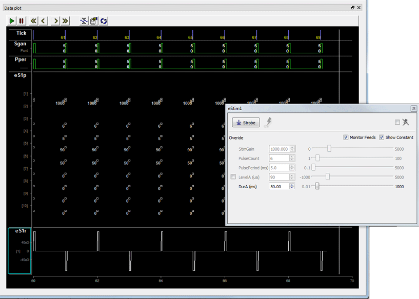 |
| Runtime Tabs with Various Stimulus Stores Enabled for Illustration |
The illustration above shows the different ways stimulus information can be stored with the Electrical Stimulation gizmo. Whichever stores you chose to include will be added to the runtime plot alongside the recording plots.
If enabled in the gizmo configuration, a control tab is added at runtime. Parameters that can be controlled dynamically are shown in black (active). You can enter a value in the field, use up and down arrows, or drag a slider to modify to parameter value.
The illustrations above and below, show the tab floated and with all the options shown. You can show only the elements you need or hide the entire control.
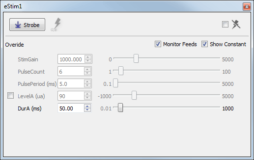 |
| eStim Runtime Tab - Floated |
Click and release the Strobe Button to trigger a manual strobe pulse.
Select the Mute Button check box to zero the stimulus signal.
Select the Monitor Feeds check box to show stimulus parameters controlled by an input signal. Also adds an Override column and check box to the left. Select the Override check box to adjust the parameter value manually instead of using the input signal.
Select the Show Constant check box to display values for parameters set to Constant. They will appear gray.
Electrical Stimulation Configuration Options
Use the options tabs to enable/disable optional features and set parameters that will be used to configure the gizmo operation and interface. Changes are not applied until you commit all settings. See The Options Area and Templates for more information on the gizmo name, source, global options, and displaying the block diagram.
General Tab
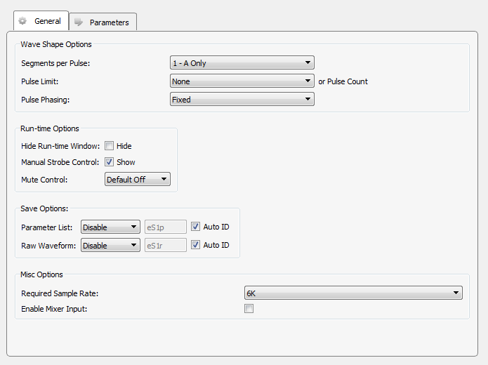 |
| General Tab |
Wave Shape Options
Segments per Pulse
Choose the number of segments that make up each pulse. Each pulse can have up to three segments, designated A, B, or C. Level and duration for each segment are configured on the Parameters tab. Examples below illustrate how segments can be used to build various waveform shapes.
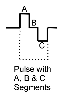 |
| Pulse Examples |
Pulse Limit (or Pulse Count)
Select how the stimulus comes to an end, that is, pulses stop. If none is selected, any pulse count value or method will be applied.
Pulse Phasing
By default, the level value of the pulse defines the phase of the stimulus. Pulse phasing can apply an alternating phase (* -1)by pulse or stimulus. If used, it will be applied at the start of a stimulation presentation or the start of each pulse.
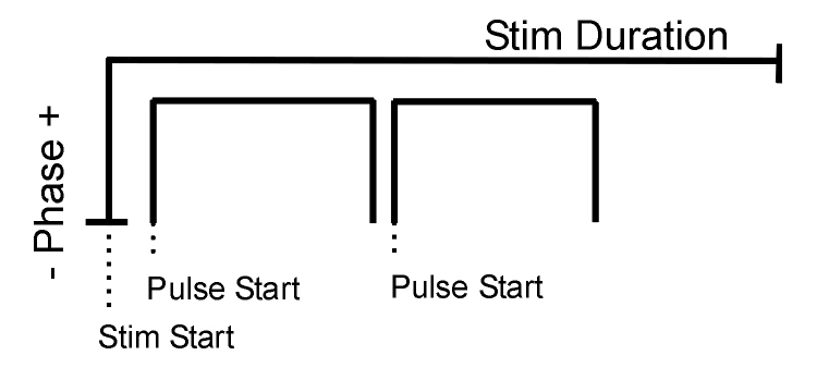 |
| Stimulus/Pulse Phase Diagram |
Hide Run-Time Windows check box
By default a runtime tab is added in preview or record mode. The contents of the tab are defined with configuration options on the General and Parameter options tab. Select the check box to hide the runtime tab.
Manual Strobe Control check box
When selected a manual strobe control is added to the runtime eStim tab.
Mute Control
Select the default behavior of the runtime mute control. Mute allows you to mute or temporarily zero the stimulus during runtime. You can choose to hide or show the control and, if show, set the default start state.
Parameter List
Select whether to store the value of all parameters, at each stimulus or pulse onset. This generates a multi-channel list of scalar values. The channels map directly to the rows of the parameters table on the Parameters tab. By default, some parameters are hidden in the table, but values are stored for all parameters.
Auto ID field and check box
A store name is generated automatically. A "/" is appended to the name to indicate when the full epoc is stored (and is not appended when only saving the onset). To use your own store name, clear the Auto ID check box.
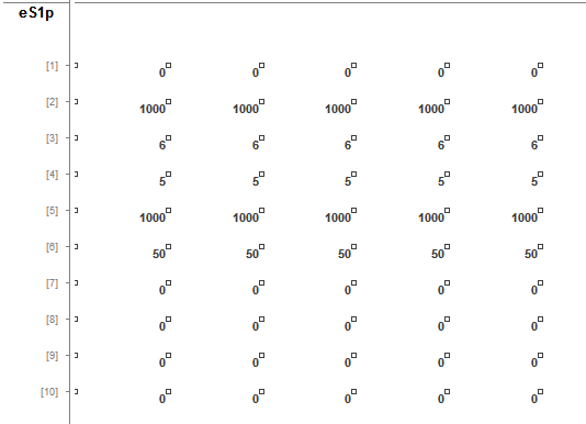 |
| Parameter List Store in the Runtime Plot |
Raw Waveform
Select whether to store a copy of the raw stimulus waveform. You can choose to store continuously or only when the stimulus is active.
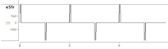 |
| Raw Stimulus Waveform Store in the Runtime Plot |
Required Sample Rate
The minimum rate required. Synapse looks through the entire experiment and your rig and sets the sample rate according to this and other limiting factors.
Parameters Tab
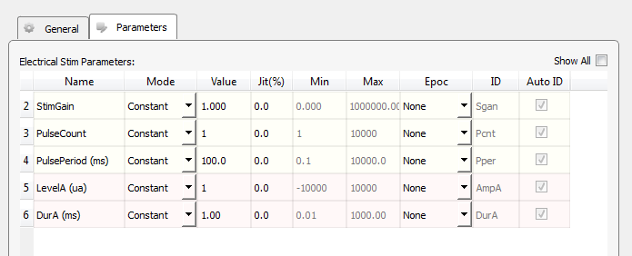 |
| Parameters Tab |
Electrical Stim Parameters
The table lists parameters relevant to configuring a stimulus. Each row represents a parameter and rows are shown or hidden in response to selections you make on the General tab. Use the Show All check box to display hidden rows.
Tip
See Using Parameters for more information on using the parameters table.
Mode
In the Mode column, you can choose to make an individual parameter Constant, controlled by a runtime Widget, or controlled by a Parameter Input (Param In) or one of two possible Scalar Input lines (Scalar In-1, Scalar In-2).
Value Columns
Enter values in the Value, Jit% (Jitter), Min, and Max columns to set the constant value or to set the initial value when a widget control will be used.
Epoc
In the Epoc column, you can choose to save the individual parameter value on stimulus or pulse onset. See the Stimulus/Pulse Phase Diagram for an illustration.
ID and Auto ID check box
Synapse automatically generates a store name. TDT recommends using Auto ID to ensure no store names are duplicated. To make your own store names, clear the Auto ID check box.
SCout-1 and SCout-2
Select the radio button in the desired row to feed the parameter to an output line.