State Maker
Common Use Cases

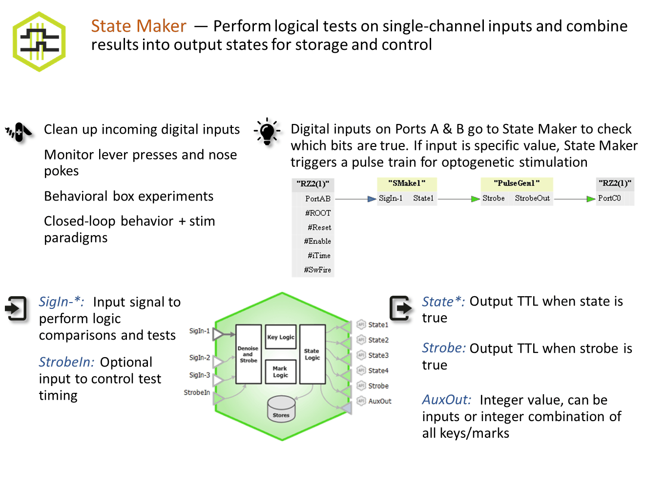
State Maker is an interface for performing logical tests on single-channel inputs and combining results into output states for storage and controlling/ triggering other gizmos for further signal processing. Use this gizmo when receiving bit codes from external devices, and to make decisions/ process gizmo output values. Used often to trigger store events or strobing other gizmos.
Gizmo Help Slides
Reference
Inputs are first conditioned to extract the interesting bits. The conditioned inputs are used in logical truth tests, which create 'keys'. Logical combinations of keys are used to create 'marks'. Logical combinations of marks and/or keys are used to create 'states', which can be sent to other gizmos and can be stored to disk. If a Strobe is used, the logic tests are only processed when the strobe is true.
State Maker Configuration Options
Inputs etc Tab
 |
| Inputs etc Tab |
Input - 1..3
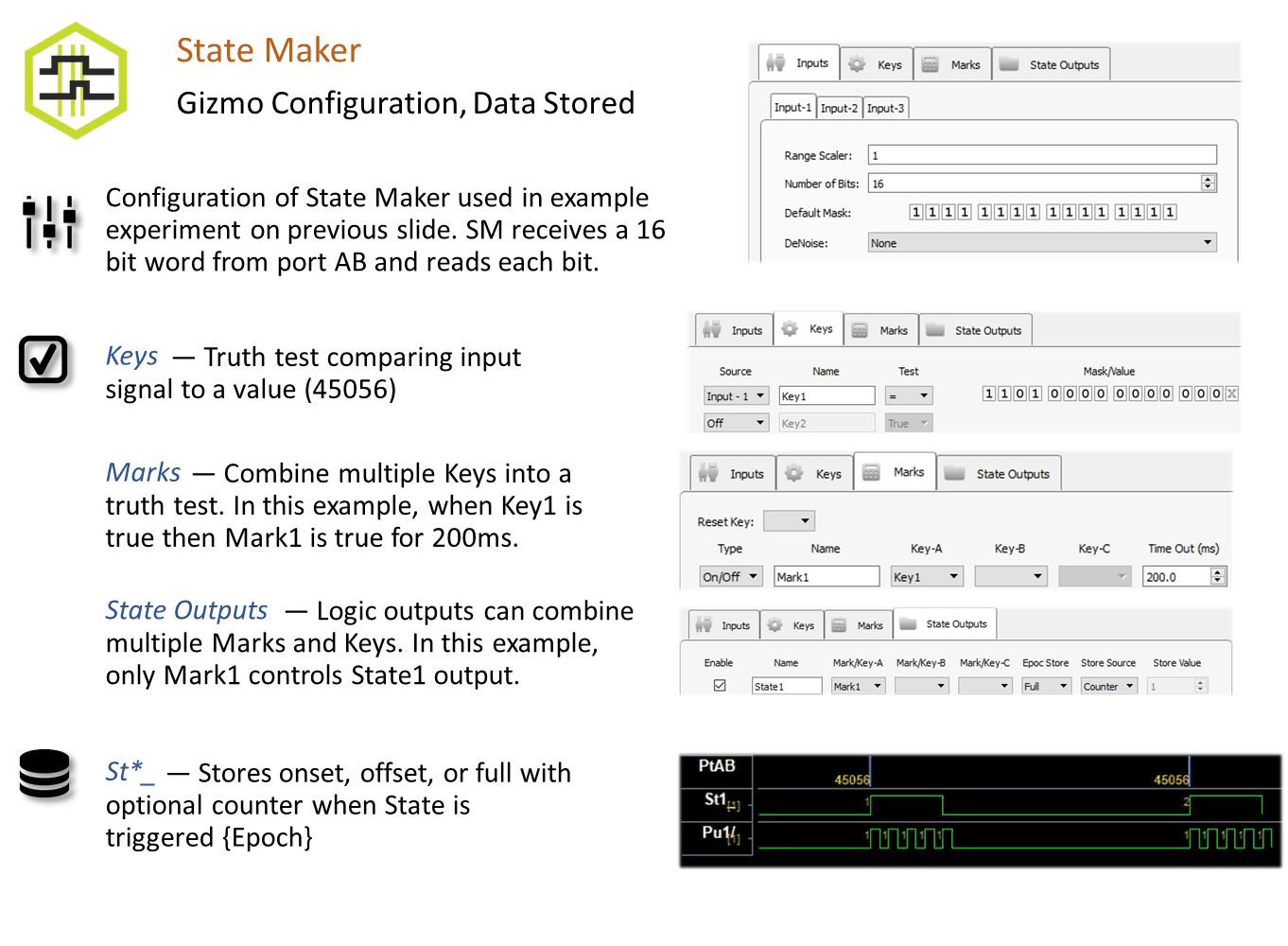
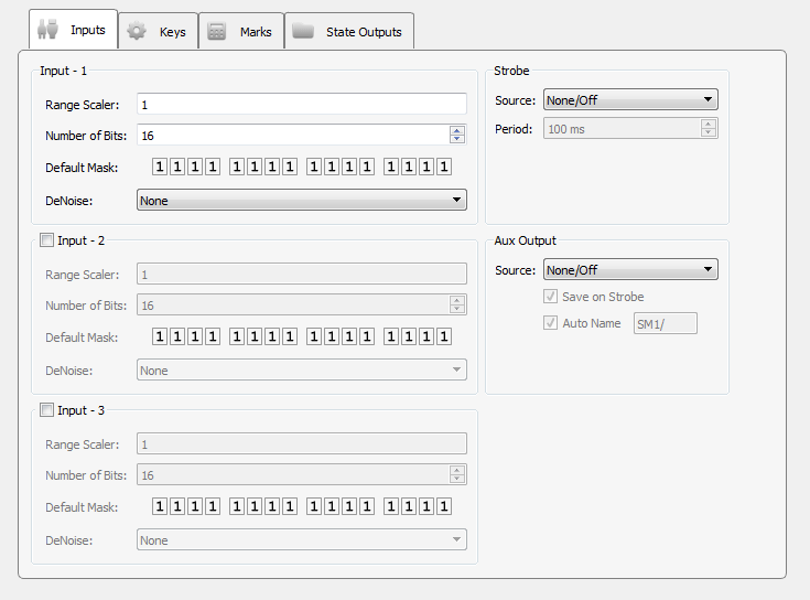
State Maker performs integer-based logic, but can accept any single channel signal (float, integer, logic). Each input is first scaled (Range Scaler), which is particularly useful if the input is a floating point signal, such as an eye tracker. Tell it the total Number of Bits in the input signal. For a logic input signal, this number will be 1.
Set the Default Mask to tell which bits to pay attention to on the input. Set a bit to X to ignore it.
DeNoise ensures the value is stable for the specified amount of time before processing it. For example, this is useful if the input is a button press on an external device being read through the digital input on the hardware. This type of signal may 'bounce' when pressed or released, which will create several rapid state changes in that moment, whereas we only want StateMaker to see a single state change on that input. Adding denoising ensures that the State Maker doesn't process these bounces as individual events and instead waits until the signal is stable for this period of time before changing the input state.
Strobe
By default, State Maker processes the inputs and updates the output states on every tick of the sample clock. Set a Strobe Source if you want to control when the logic testing takes place. The strobe can come from an Internal Timer running on the hardware, fed from an additional gizmo input (called StrobeIn), or triggered when the value of Input-1 changes (On Data Change).
Aux Output
State Maker can output any or all states generated. Set the Aux Output to output any of the input lines as a pass through or to output a key, mark, or state output (Key/Mark/State Word). If a strobe is used, the Aux Output value can also be saved on the strobe.
Keys Tab
 |
| Keys Tab |
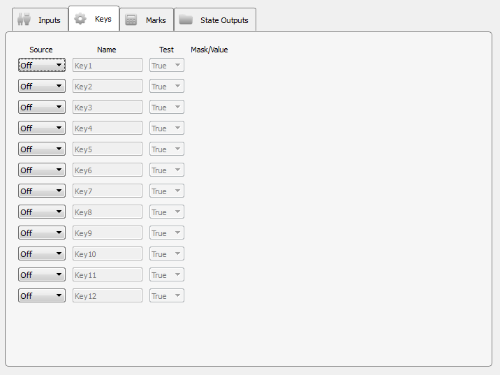
Perform up to twelve logic tests to create 'keys'. Each key uses one of the inputs as its source, and is given a meaningful name that is referenced later on the Marks and State Outputs tabs. It performs a conditional test comparing the key source to the mask/value based on the Test selection.
The Mask tells you which bits to look at or ignore. If a bit in the mask contains an 'x' icon, this bit is ignored during the logic test. If it contains a 0 or 1, that is used for the value test. When Test is 'True', the mask/value is ignored and any source value greater than 0 is considered true.
Click the bit icon to toggle between possible values, that is, 0, 1, or X.
![]()
![]()
![]()
If you would rather enter a number mask/value, right-click on a bit icon in the Mask/Value column to change the data format from binary to decimal or hexadecimal.
Marks Tab
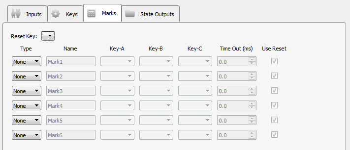 |
| Marks Tab |
Use logical combinations of keys to create up to six marks. Each mark uses at least one key as an input and is given a meaningful name that is referenced later on the State Outputs tab.
Keys defined in the Keys tab are listed in the Key-A, Key-B and Key-C drop- downs. At the bottom of the list are the same keys with a '~' prefix - these are the inverse keys, so ~Key1 means 'not Key1'.
Mark Types
The different mark types are described below. Note that any key input (Key-A, Key-B or Key-C) that is left blank is ignored.
On/Off
When Key-A is true, this mark is true and stays true until either Key-B is true or until the Time Out (ms) period has expired (if Time Out (ms) is non- zero). If Use Reset is selected, the Reset Key can also be used to turn off this mark.
And
When all keys specified in Key-A, Key-B, and Key-C are true, this mark is true.
Or
When any key specified in Key-A, Key-B, and Key-C is true, this mark is true.
Xor
When one and only one key specified in Key-A, Key-B, and Key-C is true, this mark is true.
State Outputs Tab
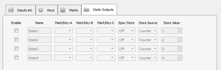 |
| State Output Tab |
Use logical combinations of keys and/or marks to create up to four states. Each state uses at least one key/mark as an input and is given a meaningful name that is used when linking to other gizmos and/or storing state values to disk. The states are determined by an 'AND' operation on Mark/Key-A, Mark/Key-B, and Mark/Key-C. Any Mark/Key drop-down left blank is ignored.
You can optionally choose to store the state onset, offset, or onset and offset timestamps into the data tank.