LR10 Lab Rat Interface Module
The Lab Rat HAL is the nexus for all interactions with the Lab Rat interface
module. The Lab Rat is only available in Synapse Lite software. The LR10 HAL is
an independent object in the Processing Tree. However, the acquisition
processing and I/O functionality are internally dependent on Corpus software and
emulated RZ2 hardware.
 |
|
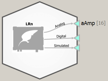
LR10 Block Diagram, showing the analog amplifier enabled |
LR10 Options
Controls for analog and digital amplifiers, synthetic neural data generation for
experiment testing, and multi I/O communications are modified within the Lab Rat
object. Here, subcomponents can be enabled or disabled, and their settings can
be adjusted prior to experimental run time. The four tabs of the LR10 are:
Analog Amp, Digital Headstage, Fake Brain, and Other I/O.
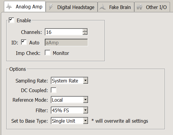
Analog Amp
The Analog Amp page controls the 16-channel analog neural input on the Lab Rat
interface module. From this page, the user can: enable/disable the amplifier,
control how many channels of input to read, and adjust the sampling rate and
filter settings of the amplifier. When the amplifier is enabled, the amplifier
ID will appear as a Gizmo output at the top of the HAL and can be connected to
other gizmos for further signal processing, with your selected channel count and
amp ID.
 |
|
LR10 Analog Amp Options |
| Option |
Description |
| Imp Check |
Show online impedance testing results for the connected electrodes. See Runtime Interface. |
| Sampling Rate |
Set the Sampling Rate to match the desired frequency band of your incoming signals (or leave at 'System Rate' if you are unsure). By default, the sampling rate matches that of the emulated RZ2. |
| DC Coupled |
Remove the 0.4 Hz high pass filter on the input signals and record DC potentials. |
| Reference Mode |
Select the mode from the drop-down menu.
Local - all channels use a single reference (pin 5 on the DB26).
Differential - each even channel acts as a reference for the odd channel before it. Note: the output channels will be mapped for you to remove duplicate channels. |
| Filter |
Set the anti-aliasing low pass filter cutoff as a percentage of the sampling rate. |
| Set to Base Type |
If you are unsure, use Set to Base Type to configure the amp with default settings based on common signal types. |
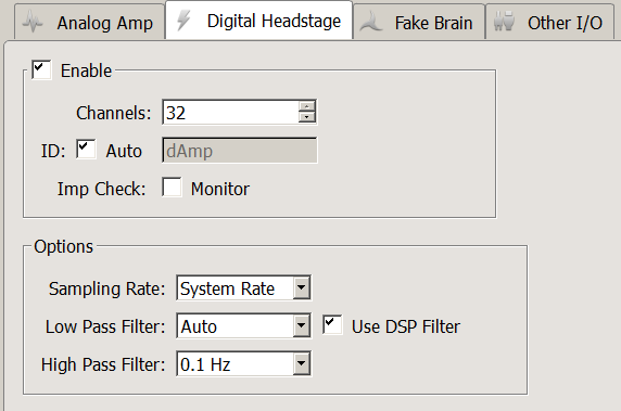
Digital Headstage
Enable the Digital Headstage when using an Intan-based digital headstage.
 |
|
LR10 Digital Headstage Options |
| Option |
Description |
| Imp Check |
Show online impedance testing results for the connected electrodes. See Runtime Interface. |
| Sampling Rate |
Set the Sampling Rate to match the desired frequency band of your incoming signals (or leave at 'System Rate' if you are unsure). By default, the sampling rate matches that of the emulated RZ2. |
| Low Pass Filter |
Choose a value for the low pass filter implemented on the digital headstage chip. If Low Pass Filter is set to "Auto," the cutoff frequency will be configured according to the conversion table below. |
| Use DSP Filter |
Adds additional low pass filtering (performed by Corpus), matched to the selected Low Pass Filter frequency. This removes high-frequency digital noise that is added by the digital headstage chip. |
| High Pass Filter |
Implemented on chip. |
'Auto' low pass filter settings for different sub amp sampling rates
Digital Amp
Sampling Rate |
LP Auto
Filter Cutoff |
| 750 Hz |
300 Hz |
| 1.5 kHz |
750 Hz |
| 3 kHz |
1.5 kHz |
| 6 kHz |
3 kHz |
| 12 kHz |
5 kHz |
| 25 kHz |
10 kHz |
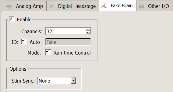
Fake Brain
The Fake Brain is a synthetic data generator. This is a useful tool for
designing experiments with well-behaved signals. The Fake Brain acts like an
amplifier, and streams generated signals from the Lab Rat into Corpus. This
means that you can connect Gizmo inputs to the Fake Brain output. Please take
care to double-check that you are not handling and saving synthetic data during
real experiments.
 |
|
LR10 Fake Brain Options |
| Option |
Description |
| Mode |
Enable the Run-time Control to change the type of generated waveforms dynamically. These include:
Normal: default mode, includes LFP and spikes.
Hash: like Normal, but spikes reduced by a factor of 2.
LFP Only: like Normal but no spikes.
Tetrode: like Normal, but spikes on each group of four channels fire synchronously.
Sync 100 Hz: spikes fire at 100 Hz on all channels.
Tone 30 Hz: A 30 Hz ~700 uV sine wave on all channels.
Tone 1 kHz: A 1 kHz ~70 uV sine wave on all channels.
Tone Ref: A 100 Hz ~700 uV sine wave on all channels. |
| Stim Sync |
Simulate inhibitory or excitatory input to the fake spike modes (Normal, Hash, Tetrode) with the Stim Sync option.
You can enable this with an external device input, like the Bit0 BNC connector on the front of the LR10, to modulate firing rate with external hardware. When the Stim Sync input is activated, certain spike shapes are inhibited (fire less) and others are excited (fire more). To control the stim sync using only the LR10, use the Gizmo Input option. |
Note
See the FB128 section of the System 3 Manual
for more information on the Fake Brain modes.
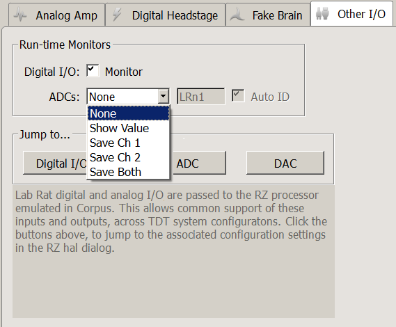
Other I/O Tab
 |
|
LR10 Other I/O Tab |
| Option |
Description |
| Digital I/O Monitor |
Shows you the logic state of all digital I/O on the Lab Rat at run time. |
| ADCs |
You can choose to save the analog inputs coming into the "A/D" connector to disk or just view them during your experiment. |
Lab Rat digital and analog I/O are passed to the emulated RZ2 processor in
Corpus. This allows common support of these inputs and outputs across TDT system
configurations. Software configuration of the multi I/O parameters is controlled
in the RZ HAL. The Jump to... section takes users to the appropriate RZ HAL page
for I/O configuration. For more information, please overview See RZ Options..
| Option |
Description |
| Digital I/O |
16 bits of digital input (8 bit-addressable, 8 word-addressable) are available. |
| ADC |
Two channels of ADC input are available as single-channel inputs or combined into a multi-channel signal for further processing. |
| DAC |
Two channels of DAC output are available as single-channel outputs or can be combined and controlled by a multi-channel signal. Each DAC channel can be tied to the output of a Gizmo, such as the Electrical Stimulation or File Stimulation gizmos. |
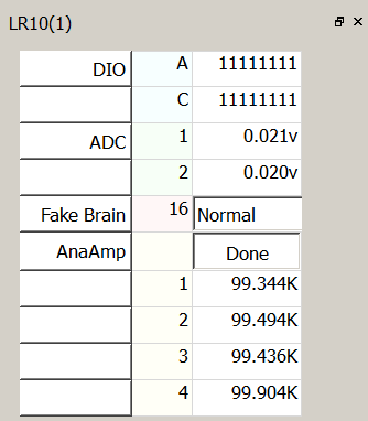
Runtime Interface
 |
|
LR10 Runtime Interface |
When Digital I/O Monitor is enabled on the Other I/O Tab, the state of all 16
bits is shown on the runtime interface in binary format.
If Show Value is selected for the ADCs option on the Other I/O Tab, the current
voltage on the ADC inputs will be shown at runtime.
If Run-Time Control Mode is enabled in the Fake Brain Tab, you can change the
fake signal type dynamically.
If the Imp Check option is enabled for the analog and/or digital headstage, use
the interface button to switch the LR10 into impedance checking mode. The
current impedance values of the connected electrode will update on the user
interface. During the impedance check, the signals returned from the amplifier
will be the value of the impedance, in MOhm. If the impedance of an electrode is above
500 kOhm, the monitor will return a value of "High Imp."
The impedance check uses a 90 nA RMS sine wave signal. The frequency depends on the
sampling rate of the sub-amplifier.
| Analog Amp Sampling Rate |
Impedance Check Frequency |
| 750 Hz |
35 Hz |
| 1.5 kHz |
70 Hz |
| 3 kHz |
140 Hz |
| 6 kHz |
280 Hz |
| 12 kHz |
560 Hz |
| 25 kHz |
1120 Hz |
| Digital Amp Sampling Rate |
Impedance Check Frequency |
| 750 Hz |
24 Hz |
| 1.5 kHz |
48 Hz |
| 3 kHz |
95 Hz |
| 6 kHz |
191 Hz |
| 12 kHz |
381 Hz |
| 25 kHz |
763 Hz |
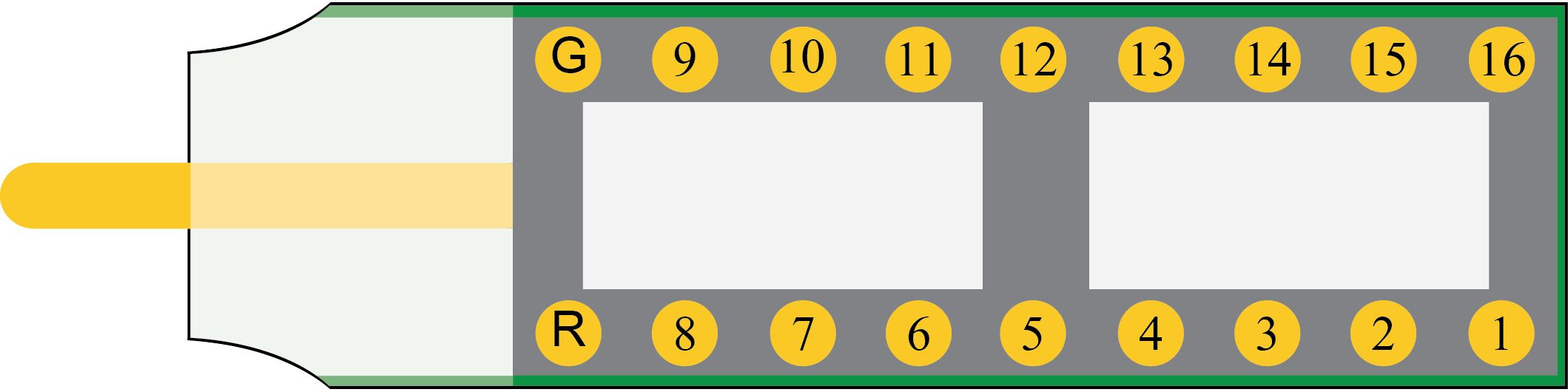
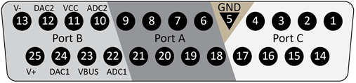
Pinouts
The pinouts are looking into the connector.
AC16LR Headstage
DB25 Connector
| Pin |
Name |
Description |
|
Pin |
Name |
Description |
| 1 |
C0 |
Port C Bit Addressable |
|
14 |
C1 |
Port C Bit Addressable |
| 2 |
C2 |
Digital I/O |
|
15 |
C3 |
Digital I/O |
| 3 |
C4 |
Bits 0, 2, 4, 6 |
|
16 |
C5 |
Bits 1, 3, 5, 7 |
| 4 |
C6 |
+3.3 V, 10 mA max per bit |
|
17 |
C6 |
+3.3 V, 10 mA max per bit |
| 5 |
GND |
Ground |
|
18 |
A0 |
Port A Word Addressable |
| 6 |
A1 |
Port A Word Addressable |
|
19 |
A2 |
Digital I/O |
| 7 |
A3 |
Digital I/O |
|
20 |
A4 |
Bits 0, 2, 4, 6 |
| 8 |
A5 |
Bits 1, 3, 5, 7 |
|
21 |
A6 |
+3.3 V, 10 mA max per bit |
| 9 |
A7 |
+3.3 V, 10 mA max per bit |
|
22 |
ADC1 |
Analog Input Channel 1
±3 V, 20 mA max |
| 10 |
ADC2 |
Analog Input Channel 2
±3 V, 20 mA max |
|
23 |
VBUS |
+5 V, 150 mA max |
| 11 |
VCC |
+3.3 V, 250 mA max |
|
24 |
DAC1 |
Analog Output Channel 1
±3 V, 20 mA max |
| 12 |
DAC2 |
Analog Output Channel 2
±3 V, 20 mA max |
|
25 |
V+ |
+3.3 V, 150 mA max |
| 13 |
V- |
-3.3 V, 150 mA max |
|
|
|
|
| Pin |
Name |
Description |
|
Pin |
Name |
Description |
| 1 |
A1 |
Analog Input Channels |
|
14 |
V+ |
Positive Voltage (+2.5 V) |
| 2 |
A2 |
|
|
15 |
GND |
Ground |
| 3 |
A3 |
|
|
16 |
GND |
Ground |
| 4 |
A4 |
|
|
17 |
V- |
Negative Voltage (-2.5 V) |
| 5 |
Ref |
Reference |
|
18 |
HSD |
Headstage Detect |
| 6 |
HSD |
Headstage Detect |
|
19 |
HSD |
|
| 7 |
A5 |
Analog Input Channels |
|
20 |
A6 |
Analog Input Channels |
| 8 |
A7 |
|
|
21 |
A8 |
|
| 9 |
A9 |
|
|
22 |
A10 |
|
| 10 |
A11 |
|
|
23 |
A12 |
|
| 11 |
A13 |
|
|
24 |
A14 |
|
| 12 |
A15 |
|
|
25 |
A16 |
|
| 13 |
AltRef |
Not Used |
|
26 |
NC |
Not Used |
Note
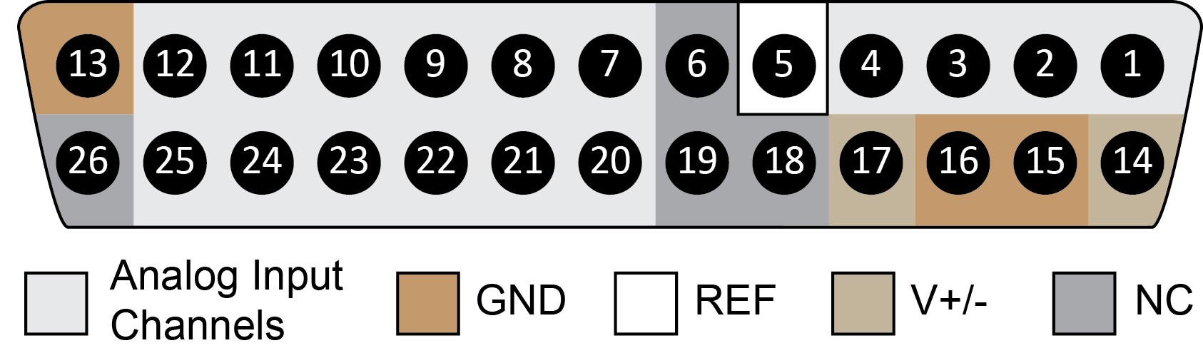
There are 8 (+) channels and 8 (-) channels per DB26 connector.
| Pin |
Name |
Description |
|
Pin |
Name |
Description |
| 1 |
A1(+) |
Analog Input Channels |
|
14 |
V+ |
Positive Voltage (+2.5 V) |
| 2 |
A1(-) |
|
|
15 |
GND |
Ground |
| 3 |
A2(+) |
|
|
16 |
GND |
Ground |
| 4 |
A2(-) |
|
|
17 |
V- |
Negative Voltage (-2.5 V) |
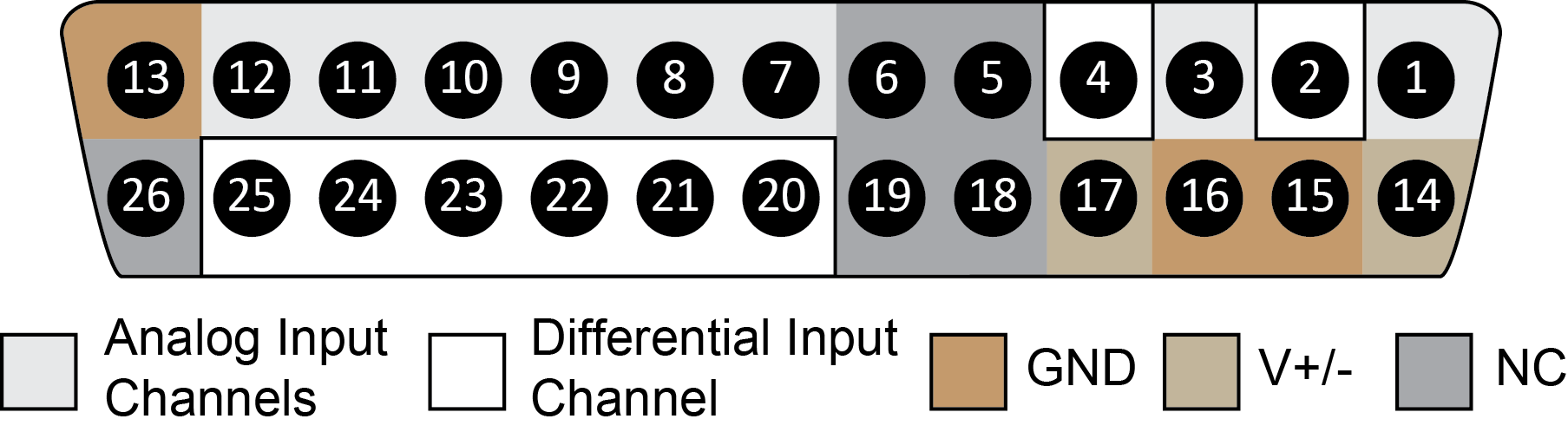
| 5 |
NC |
Not Used |
|
18 |
HSD |
Headstage Detect |
| 6 |
HSD |
Headstage Detect |
|
19 |
HSD |
|
| 7 |
A3(+) |
Analog Input Channels |
|
20 |
A3(-) |
Differential Input Channels |
| 8 |
A4(+) |
|
|
21 |
A4(-) |
|
| 9 |
A5(+) |
|
|
22 |
A5(-) |
|
| 10 |
A6(+) |
|
|
23 |
A6(-) |
|
| 11 |
A7(+) |
|
|
24 |
A7(-) |
|
| 12 |
A8(+) |
|
|
25 |
A8(-) |
|
| 13 |
GND |
Ground |
|
26 |
NC |
Not Used |
Note
Consult tech note 0896
before attempting to make any custom connections. Use the PZ5 instructions.