Fiber Photometry for non-RZ10 Processors
Common Use Cases

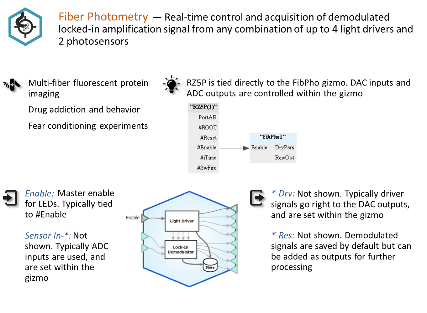
Real-time control and acquisition of demodulated locked-in amplification signal from any combination of up to 4 light drivers and 2 photosensors. This is the primary gizmo used in fiber photometry setups using processors other than an RZ10 or RZ10x. Record up to 8 demodulated signals with raw photosensor output too.
Gizmo Help Slides
Reference
The Fiber Photometry gizmo, when used with processors that are not the RZ10, includes designtime and runtime control of up to four voltage output signals to drive external light drivers. It uses lock-in amplification to measure the real- time power of the resulting fluorescence response at the light driving frequencies. It controls up to four light driver signals and reads two photosensors via the RZ analog inputs.
The Runtime Interface
Runtime Plot
A plot is added to the runtime window for visualization.
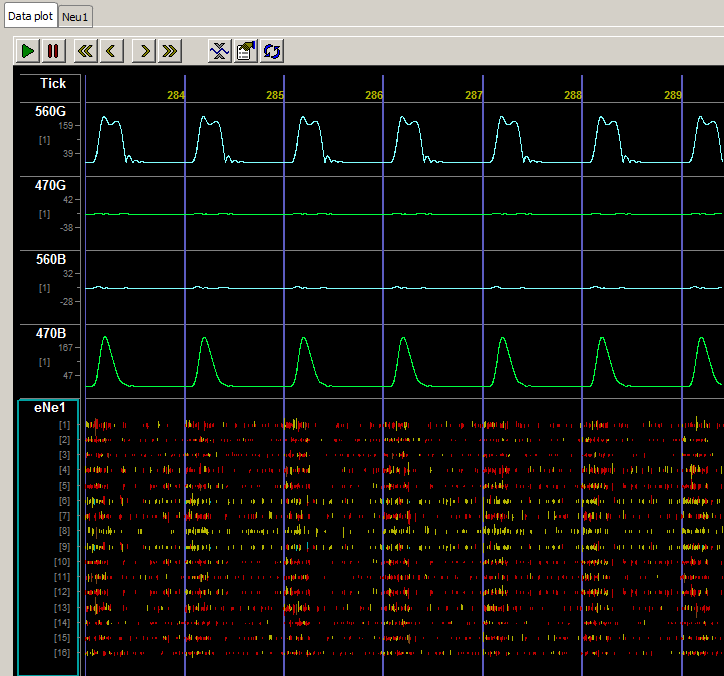 |
| Flow Plot Showing Demodulated Responses |
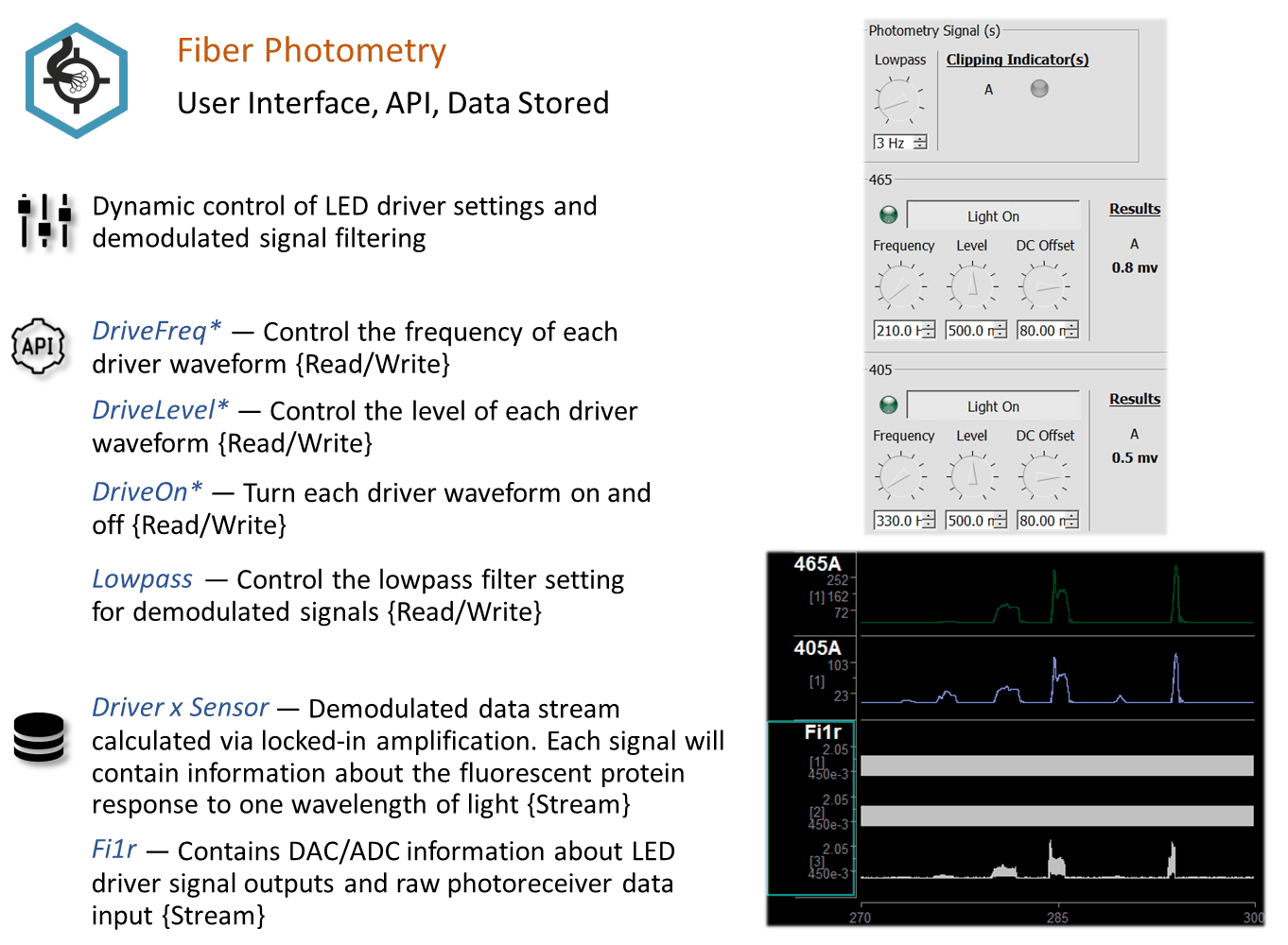
The subplots shown in a runtime plot represent data storage you chose in the designtime options. In the example above, the streamed data shows the resulting power output (such as Dv1A) at the frequency of interest when comparing the selected driver (such as Drv1) to the selected sensor input (such as sensor A). Simultaneous neural recordings from a different gizmo are integrated in the plot for a quick visual comparison. The Fiber Photometry gizmo also stores and displays broadband raw input signals and driver parameters, depending on selections made at designtime.
Runtime Controls
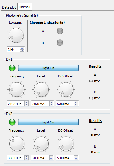 |
| Runtime Interface |
The runtime window includes:
Fiber Photometry Configuration Options
See The Options Area and Templates for more information on the gizmo name, source, global options, and displaying the block diagram.
Driver(s) Tab
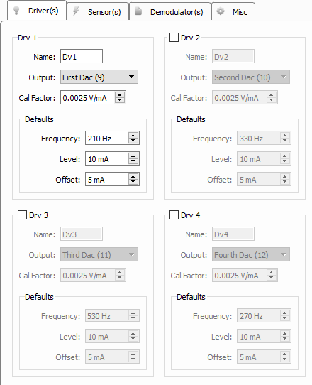 |
| Driver(s) Tab |
Sensor(s) Tab
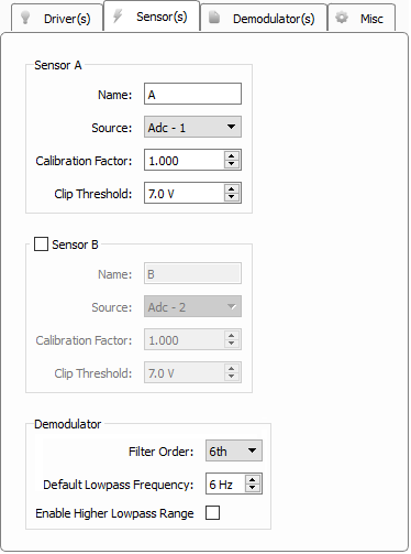 |
| Sensor(s) Tab |
Demodulator(s) Tab
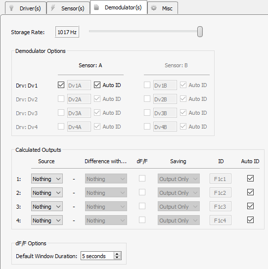 |
| Demodulator(s) Tab |
Storage Rate
Set the storage sampling rate for the demodulated and calculated signals configured on this tab.
Demodulator Options
Use the matrix of check boxes to select the combinations of sensors and drivers that will be used for demodulation. All available sensor signals can be demodulated against all light driver signals if desired.
Calculated Outputs
Perform up to four real-time calculations on the demodulated data streams. Choose a Source demodulated signal, optionally subtract another demodulated signal in the Difference with... column, and optionally perform a delta F over F calculation on it (dF/F checkbox) to compare the strength of the signal relative to the baseline.
Saving
The calculated signal is available as a gizmo output so other gizmos can attach to it and do further processing in real-time. The calculated signal can also be optionally shown on the Flow Plot at runtime, and optionally be saved to disk as well.
dF/F Options - Default Window Duration
Sliding average window size used as the baseline for the delta F over F computation.
Misc Tab
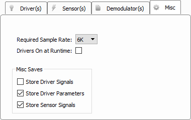 |
| Misc Tab |
Required Sample Rate
Tells the RZ what minimum sample rate this gizmo requires. Typically 6K is enough. Only increase this if the driver frequency needs to go beyond 1-2 kHz for your experiment, which is rarely done.
Drivers On at Runtime
When selected, output driving signals are "on" when recording begins. Otherwise, light drivers must be turned on manually in the runtime interface.
Store Driver Signals
Stores the signals used to drive the LEDs at the RZ system rate. The store name is the first two letters of the gizmo name, followed by the last letter of gizmo name, followed by 'd' (default 'Fi1d'). One channel per light driver.
Store Driver Parameters
All light driver parameters are timestamped and stored to disk two seconds after a change has been made to any of the driver parameters in the runtime user interface.
Store Sensor Signals
Stores the raw sensor signals at the RZ system rate. The store name is the first two letters of the gizmo name, followed by the last letter of gizmo name, followed by 'r' (default 'Fi1r'). One channel per sensor.