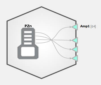
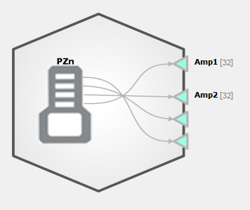
PZ Block Diagrams, showing a single amp (left) and sub amps (right).
The PZ amplifier HAL reads data from a connected PZn amplifier. The options vary
for each amplifier model. The PZ5 amplifier can have up to four logical sub
amps; each sub amp is individually configurable and forms a multi-channel
floating point data sources that can be linked to other gizmos. All other PZs
have one multi-channel floating point data source.
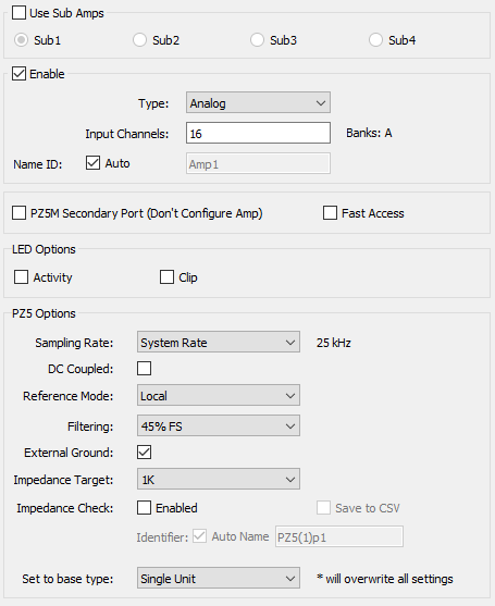
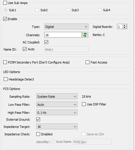
PZ5 Options
PZ5 Analog and Digital Options.
Option
Description
Use Sub Amps check box
Select to divide input channels into logical sub amps that can be used to record different types of signals, at different rates, referencing modes, and other settings.
Sub Amps radio buttons
Select a radio button to view and edit settings for the corresponding sub amp: Sub1, Sub2, Sub3, or Sub4. When sub amps are used, all of the below configuration options apply only to the selected sub amp. Each sub amp that will be used must be configured separately. If a conflict or error is detected as a result of any changed settings, Synapse displays the relevant sub amp settings and a red warning.
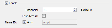
Enable
Select to enable the selected sub amp.
Type
Use an Analog or Digital amp board. When using Digital Amps, specify the number of boards. Selectable values are limited by the Rig configuration.
Channels
Type or click arrow keys to set the number of channels. The channel count must be at least four and must be a multiple of 2. The corresponding physical bank of channels on the PZ5 is displayed to the right. Note: In Differential Reference Mode, the channels from the PZ5 sub-amp are mapped for you to remove duplicates.
Name ID
Choose the name for this sub amp data source that will be visible to other gizmos.
Option
Description
PZ5M Secondary Port (Don't Configure Amp)
When using a PZ5M with either 256 or 512 channels, two PZ5 HALs may be specified in the Rig Editor, one for each fiber optic connection from the PZ5M. Only the fiber connected to the Primary port can configure the PZ5M. Use this check box on the PZ5 HAL connected to the Secondary port on the PZ5M. This setting disables the HAL configuration options and only reads the channel data from the port.
Fast Access
For a PZn connected to a DSPP card, select to perform 16-bit data reads to reduce cycle usage on the DSP.
LED Activity
Tell the PZ5 whether to flash the green activity LEDs on its front panel when activity is detected
LED Clipping
Tell the PZ5 whether to flash the red clipping LEDs when the signal is close to saturating the amplifier
Option
Description
Sampling Rate
Set the Sampling Rate to match the desired frequency band of your incoming signals (or leave at 'System Rate' if you are unsure). By default, the sampling rate matches that of the RZ.
External Ground
Connect this sub-amp ground to the external ground plug on the physical PZ5 device. Caution: When using multiple sub-amps make sure they aren't all sharing the External Ground connection or else they won't be isolated!
DC Coupled
Remove the 0.4 Hz high pass filter on the input signals and record DC potentials.
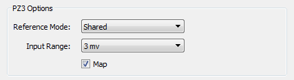
Reference Mode
Select the mode from the drop-down menu. Local - each bank of 16 uses its own reference (pin 5 on the DB26). Shared - all channels in sub-amp share the same reference (pin 5 of first bank in sub-amp). None - the ground connection is used as the reference. Differential - each even channel acts as a reference for the odd channel before it. Note: the output channels will be mapped for you to remove duplicate channels.
Filtering
Set the anti-aliasing low pass filter cutoff as a percentage of the sampling rate.
Impedance Target
This only affects the displayed impedance text colors on the touchscreen when running an impedance check. Must be using a passive headstage to run impedance check.
Impedance Check
Enable run-time impedance check
Save to CSV
Log impedance values into CSV file stored within the block folder whenever an impedance check runs
Set to base type
If you are unsure, use Set to Base Type to configure the amp with default settings based on common signal types.
Option
Description
Use Sub Amps check box
Select to divide input channels into logical sub amps that can be used to record different types of signals, at different rates, filters, and other settings
Sub Amps radio buttons
Select a radio button to view and edit settings for the corresponding sub amp: Sub1, Sub2, Sub3, or Sub4. When sub amps are used, all of the below configuration options apply only to the selected sub amp. Each sub amp that will be used must be configured separately. If a conflict or error is detected as a result of any changed settings, Synapse displays the relevant sub amp settings and a red warning.
Enable
Select to enable the selected sub amp
Type
Use an Analog or Digital amp board. When using Digital Amps, specify the number of boards. Selectable values are limited by the Rig configuration.
Channels
The channel count must be at least four and must be a multiple of 2. The corresponding physical banks on the PZ5 are displayed to the right. Click the Refresh button to automatically detect the connected headstage count (your RZ hardware must be turned on and connected for this to work).
Name ID
Choose the name for this sub amp data source that will be visible to other gizmos
Option
Description
PZ5M Secondary Port (Don't Configure Amp)
When using a PZ5M with either 256 or 512 channels, two PZ5 HALs may be specified in the Rig Editor, one for each fiber optic connection from the PZ5M. Only the fiber connected to the Primary port can configure the PZ5M. Use this check box on the PZ5 HAL connected to the Secondary port on the PZ5M. This setting disables the HAL configuration options and only reads the channel data from the port.
Fast Access
For a PZn connected to a DSPP card, select to perform 16-bit data reads to reduce cycle usage on the DSP
Headstage Detect
Tell the PZ5 whether to indicate the headstage channel count via the front panel LEDs
Option
Description
Sampling Rate
Set the Sampling Rate to match the desired frequency band of your incoming signals (or leave at 'System Rate' if you are unsure). By default, the sampling rate matches that of the RZ.
External Ground
Connect this sub-amp ground to the external ground plug on the physical PZ5 device. Caution: When using multiple sub-amps make sure they aren't all sharing the External Ground connection or else they won't be isolated!
AC Coupled
Apply a 0.4 Hz high pass filter to the incoming signals
Low Pass Filter
Select a cutoff frequency for a lowpass filter that is implemented on the digital headstage. Set to 'Auto' to match it to the sub-amp sampling rate. See table below.
Use DSP Filter check box
Add an additional lowpass digital filter implemented on the RZ, set to the same frequency as the Low Pass Filter setting above, to remove high frequency digital noise from the incoming signal that was added by the digitizing chip.
High Pass Filter
Select a cutoff frequency for a highpass filter that is implemented on the digital headstage
Impedance Target
Use to intelligently control the impedance checking circuit on the headstage based on your target impedance
Impedance Check
Enable run-time impedance check
Save to CSV
Log impedance values into CSV file stored within the block folder whenever an impedance check runs
'Auto' low pass filter settings for different sub amp sampling rates
Sampling Rate
LP Auto Filter
750 Hz
300 Hz
1.5 kHz
750 Hz
3 kHz
1.5 kHz
6 kHz
3 kHz
12 kHz
5 kHz
25 kHz
10 kHz
See the PZ5 section of the System 3
Manual
for more information about configuring and using the PZ5 amplifier.
PZ2 / PZ3/ PZ4 Options
Option
Description
Channels
Type or click arrow keys to set the number of channels.
Fast Access
For a PZ2 connected to a DSPP card, select to perform 16-bit data reads to reduce cycle usage on the DSP.
Name ID
Choose the name for this data source that will be visible to other gizmos.
Option
Description
Channels
Type or click arrow keys to set the number of channels.
Fast Access
For a PZ3 connected to a DSPP card, select to perform 16-bit data reads to reduce cycle usage on the DSP.
Name ID
Choose the name for this data source that will be visible to other gizmos.
Reference Mode
Select the mode from the drop-down menu. Shared - all channels use a separate shared reference. Differential - each even channel acts as a reference for the odd channel before it.
Input Range
Select the desired maximum input range.
Map
(Recommended) Select to remove the even channels and use only the signal channels in the data source output.
See the PZ3 section of the System 3
Manual for more
information about the operational modes of the PZ3 amplifier.
Option
Description
Channels
Type or click arrow keys to set the number of channels.
Fast Access
For a PZ4 connected to a DSPP card, select to perform 16-bit data reads to reduce cycle usage on the DSP.
Name ID
Choose the name for this data source that will be visible to other gizmos.
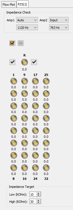
Runtime Interface
When Impedance Check is checked, a user interface appears at runtime.
The PZ5 tab provides an interface for impedance checking on all channels. The
display represents the stimulation channels divided into banks of eight
channels, broken up by sub-amplifier.
The dropdowns at the top define which type of inputs to check and the probe frequency.
If a reference electrode is used in the subamp configuration, an LED for the reference
is shown with that subamp and it is an available test option. If there are more than one
type of input, 'Auto' loops through all of them during the impedance check.
Running the Impedance Check
Run an impedance check on selected sub-amplifier. The PZ5 enters impedance check
mode and the values are displayed on the interface.
Check All. Run an impedance check on all sub-amps as described above.
Stop Checking. Stops the impedance checking prematurely.
Results of impedance check are indicated by color: below low impedance threshold
(green), above high impedance threshold (red), between low and high impedance
thresholds (yellow). The actual impedance values (in kOhm) are displayed beneath
each indicator.