PZ5 NeuroDigitizer
PZ5 Overview
The PZ5 is a multi-modal NeuroDigitizer suitable for recording a broad range of biological potentials. Its analog input boards combine the functionality of the PZ2 and PZ3 amplifiers in a single device that can be used for both high and low impedance input signals simultaneously. The PZ5 may also include digital input boards for inputting signals from TDT's ZD or OD Intan-based digitizing headstages, or an Intan RHD2000 amplifier board with up to 128 channels.
Analog input boards oversample the signal with very fast instrumentation grade converters. TDT's custom hybrid A/D circuit yields 28 bits of resolution and unparalleled dynamic range. Optional DC coupling offers zero phase distortion across the signal bandwidth. Sampling rate and down-sampling filters can be optimized on each logical amplifier for the intended input type to optimize signal fidelity. The ±500 mV input range is large enough to accept any biological potential and most stimulus artifacts without saturating.
The PZ5 analog inputs are organized into 16-channel banks. Each bank is electrically isolated, meaning the ground and reference channels are not inherently shared between banks. Multiple banks can be grouped into a single logical amplifier that shares the same settings and ground/reference among each bank in the logical amplifier. There are several different referencing modes; each logical amplifier can use the ground as a reference, use a shared reference, use a unique reference on each bank or implement full per-channel differential referencing.
Digital inputs are used exclusively with RHD2000 series amplifier boards and SPI Interface Cables, available from Intan Technologies. Each input serves as a bank of channels and may be up to 128 channels, depending on the connected amplifier board. Each digital board can be its own logical amplifier, isolated from the other boards, or be grouped with other digital boards in a larger logical amplifier configuration.
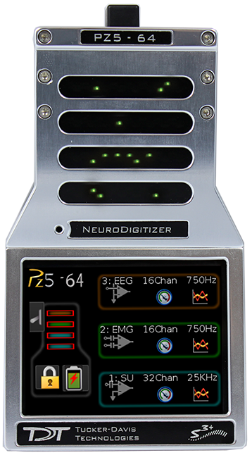
A touchscreen interface provides immediate preview of inputs, impedance checking and real-time control and configuration options for each amplifier bank.
The PZ5 is available in 32, 64, 96, or 128 analog channel models. The PZ5 is also available with 2 or 4 digital inputs and models that combine 32 or 64 analog input channels with 2 or 4 digital inputs. The PZ5 can support a total of up to 128 analog channels or up to 256 digital channels or up to 256 mixed channel types. The total number of channels is generally reduced to 128 at higher sampling rates, up to 50 kHz. See Sampling Rate and Digital Input Channels for more information.
Note
To record at ~50 kHz on 128 or more channels, see PZ5 Software Control for more information.
System Hardware
The PZ5 accepts inputs from a variety of electrode/headstage combinations via the back-panel. Each analog board has a mini-DB26 connector that accepts 16 recording channels (or 8 differential channels) along with ground and reference. Digital boards have a 12-pin Omnetics connector for Intan headstages and can accept up to 128 digital channels each. The PZ5 can return at most 256 recording channels to the RZ base station.
Analog signals are digitized and transmitted to the RZ base station for further processing via a single fiber optic connection. Configuration information is also sent from the RZ to the PZ5 across the fiber optic connection. The PZ5 can connect to the 'PZ Amplifier' input on an RZ2 base station, or directly to any RZDSP-P card or optical QZDSPO quad card on any RZ base station.
A standard recording configuration includes electrodes appropriate to the input signals, a breakout box or one or more Z-Series headstages (such as ZC32), a PZ5 and an RZ base station.
The diagram below illustrates this flow of data and control information through the analog system.
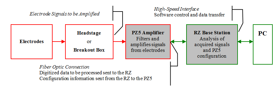 |
| PZ5 Data and Control Flow Diagram |
Hardware Setup
TDT recommends fully charging the PZ5 before use. The PZ5 battery charger connects to the round female connector located on the back panel.
Important
To avoid introducing EMF noise, DO NOT connect the charger to the PZ5 while collecting data.
A 5-meter paired fiber optic cable is included to connect the PZ5 to the base station. The connectors are color coded and keyed to ensure proper connections.
The diagram below illustrates the connections necessary for PZ5 operation.
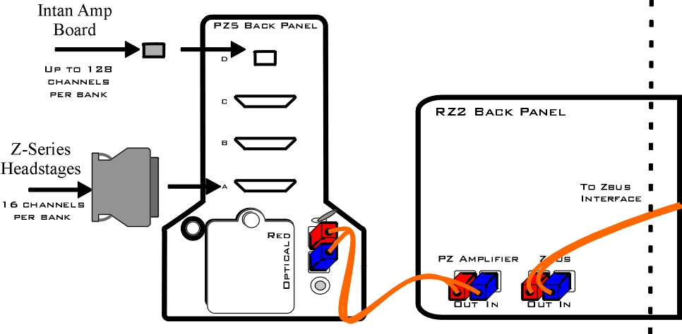 |
| System Connection Diagram for PZ5 with RZ2 |
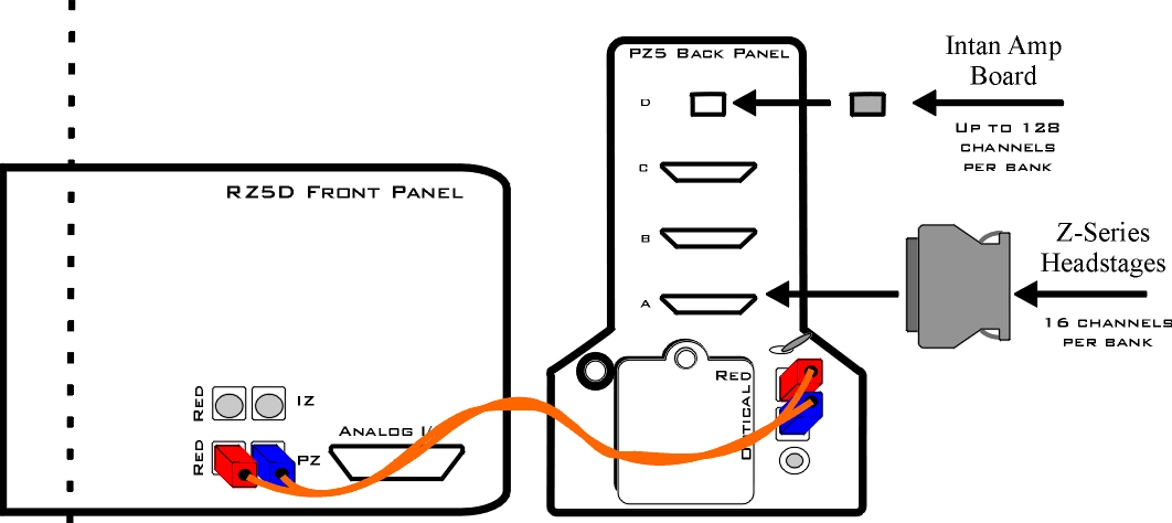 |
| System Connection Diagram for PZ5 with RZ5D |
Connecting Headstages and Electrodes
Analog signals are input via multiple mini-DB26 connectors on the PZ5 back panel. For high impedance recordings, one or more Z-Series headstages can be connected to the input connectors on the PZ5 back panel. For low impedance recordings, an S-BOX input splitter or LI-CONN low-impedance connector can be used. Alternately, custom connectors and a breakout box with a male mini-DB26 connector can be used. If using custom connectors, see Pinout Diagrams.
Digital signals are input via Intan connectors on the PZ5 back panel.
Powering ON/OFF
To turn the PZ5 on, move the toggle switch located on the back panel of the PZ5 to the ON position.
Physical Amplifier
All PZ5 analog input channels are organized into groups of 16 channel banks, with each bank corresponding to a rear panel headstage connector (labeled alphabetically from bottom to top) and a front panel LED display.
Digital input channels are associated with a digital board corresponding to a rear panel digital input connector (labeled from bottom to top following, alphabetically, any analog input connectors). Each digital board is a bank that can comprise 16, 32, 64, 96, or 128 channels, depending on the connected Intan amplifier board(s).
Each bank is electrically isolated and can be independently configured or grouped with other banks and defined as a logical amplifier. Analog and digital boards cannot be combined together.
Logical Amplifiers
Though each bank has its own ground and reference, a single ground and reference can also be defined and shared across all banks of the logical amplifier. See Analog Recording Reference Modes for analog input banks.
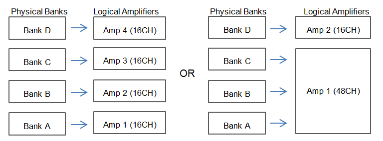 |
| Two Possible Logical Amplifier Configurations for a PZ5-0-64 64 Channel (all analog input) |
Digital boards can be configured individually or grouped to share a single ground and use common filter settings and sampling rate.
Note
Channel numbering on digital input banks can be non-sequential when sampling at 50 kHz. See Sampling Rate and Digital Input Channels.
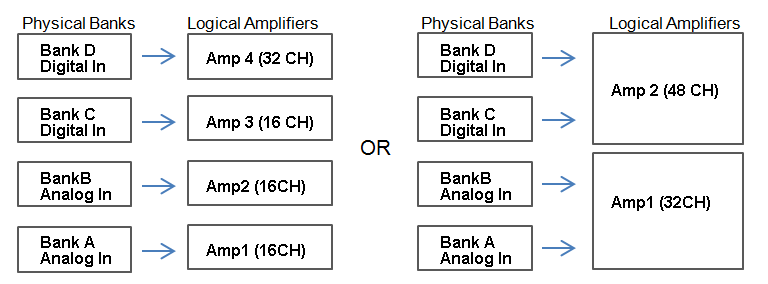 |
| Two Possible Logical Amplifier Configurations for a PZ5-64-2 (with two digital inputs) |
Logical amplifier configurations can be defined using the front panel interface (see PZ5 Touchscreen), in Synapse, or in RPvdsEx using the PZ5_Control macro. The PZ5-0-32 model can have a maximum of two logical amplifiers configured. All other PZ5s can have a maximum of four logical amplifiers.
Analog Recording Reference Modes
The PZ5 supports four referencing modes for each analog input logical amplifier: Local, Shared, None and Differential. See Pinout Diagrams.
Sampling Rate and Onboard Filters
The sampling rate of each logical amplifier is adjustable (max 50 kHz, min 750 Hz) and should be set to a value appropriate for the signal of interest. Reducing the sampling rate when acquiring low-frequency analog signals yields higher bit resolution and improved signal-to-noise. Use the Amp Type Presets as a guide for determining what sampling rate to use for each logical amplifier.
The onboard down-sampling filters are used to further reduce the noise from frequencies above the band of interest and can be set to a percentage of the sampling rate (max 45%, min 10%). Adjusting the sampling rate and filter for each logical amplifier to match your desired signal gives you the best possible signal fidelity.
Sampling Rate and Digital Input Channels
When a logical amplifier contains digital inputs, the sampling rate should be set to a value appropriate for the connected Intan amplifier board. Sampling rates at or above 50 kHz reduce the number of channels available on the amplifier boards.
At 50 kHz the 32 channel amplifier board is limited to 20 channels and the 64 and 128 channel boards are limited to 40 channels, at the time of this writing. The maximum aggregate number of channels is 256 channels at up to 25 kHz, or 128 channels at up to 50 kHz.
It is also important to note that, while the Intan board channel numbers are normally sequential and offset by the number of analog inputs in the amplifier, sampling at or above 50 kHz may also affect channel numbering.
At 50 kHz the native channel numbers per board are 1-20 and 33-52. These channel numbers are then offset by the number of channels existing in the lower banks of the PZ5. Also see Input Connectors.
Amp Type Presets


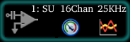
The PZ5 touchscreen interface uses representative diagrams to enable users to identify the configuration of the amplifier at a glance. The table below explains the parts of the diagram and what each represents.
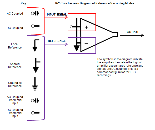 |
| PZ5 Signal/Reference Diagram |
PZ5 Software Control
All PZ5 configuration and control of data acquisition is managed through Synapse. The PZ5 object configures the analog and digital headstage recording inputs. Please see the Synapse Manual for more information.
Note
For RPvdsEx circuit design (OpenEx users), the TDT drivers installs the
PZ5_Control circuit macro in C:\TDT\RPvdsEx\Macros\Device\PZ5_NeuroDigitizer. See
the Legacy System 3 Manual
for circuit design.
Recording 128 Channels at 50 kHz
Due to the PZ5's high bit resolution and recording capabilities, data should always be stored as 32-bit floating point. However, when storing 128 channels at 50 kHz sampling rate, you must use the Short (16 bits) format due to bandwidth constraints. This means the data will be scaled and converted into an integer before storage, which narrows the dynamic range of the acquired signals. In this case, all DC offsets must be removed before the data is stored. You can either filter out the DC offset with a Neural Stream Processor gizmo in Synapse or use AC coupling on the logical amplifier if you are storing the raw signal direct from the PZ5.
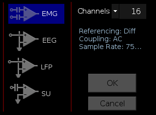
PZ5 Touchscreen
The PZ5 touchscreen can be used to add logical amplifiers, check impedance, preview waveforms in real-time. It also provides access to the PZ5 settings, such as the screen auto lock and auto sleep features, as well as tools for viewing system information, such as battery status, and updating the device software.
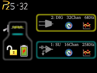 |
| Main Configuration Screen |
The main configuration screen includes the following:


Impedance Checking Screen
Important
The impedance checking feature of the PZ5 can and should only be used with a passive headstage or direct connection to the electrodes.

Enter the Impedance Checking screen by touching this icon on an existing logical amplifier on the Main Configuration screen. The logical amplifier number and amp type are displayed in the top-left corner, for example 1:EEG.
Select the type of connections to measure (Probing options) and choose a target impedance value (Target) to color code the measured impedance value text. During impedance checking, All connections in the selected set are tested in parallel and the impedance is color-coded relative to the user-defined target impedance.
A limited set of channels are visible at any one time. Swipe vertically on the touchscreen to scroll the visible channels.
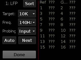
Settings include:
Waveform Display Screen

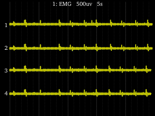
Enter the Waveform Display screen by touching this icon on an existing logical amplifier on the Main Configuration Option screen. The displayed waveform is decimated for plotting and high pass filtered so all channels can be shown on the same voltage scale. If the logical amplifier is DC Coupled, the DC offset is displayed as a value on the right side of each plot line (in mV).
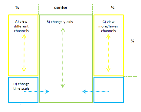 |
| Waveform Display Touchscreen Controls |
Important
To return to the Main Configuration screen, swipe three fingers across the screen in any direction. On the Main Configuration screen, a three finger swipe will turn off the display.
Manual Configuration
The logical amplifier configuration defined in Synapse is sent to the PZ5 and applied when the recording begins. However, the touchscreen interface can also be used to configure logical amplifiers on-the-fly.

For analog amplifiers, touch the + icon to add a logical amplifier. Set the Amp Type and number of channels in the screen that follows. See Amp Type Selection Screen for more information. Adjust amplifier configuration options in the next screen. See Configuration Options Screen for more information.
For digital amplifiers, the + icon has a square wave through it. Set the number of digital boards to include in the logical amplifier and the amplifier configuration options in the screen that follows. See Configuration Options Screen for more information.
Amp Type Selection Screen
Enter the Amp Type Selection screen by touching the + icon on the Main Configuration screen or by touching the Amp Type button on the Configuration Options Screen for an existing logical amplifier.
Select the Amp Type and set the number of channels in the logical amplifier (by banks of 16 channels for analog amplifiers).
Configuration Options Screen

Enter the Configuration Options screen after selecting the Amp Type when adding a new logical amplifier, or by touching the Amp Icon on an existing logical amplifier on the Main Configuration screen.
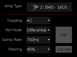
Analog Input Amp Settings
Each Amp Type includes preset values for each setting. The Configuration Options Screen lets you modify them.
Digital Input Settings
Battery Status

Press the Battery Status icon to display battery information:
Note
The Battery Level is also mirrored on the RZ2 LCD display when the PZ5 is connected to the PZ Amplifier port on the back of the RZ2.
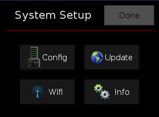
System Setup Screen
The System Setup screen is displayed by touching the PZ5 logo on the top-left of the Main Configuration screen.
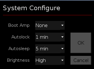
System Configure Screen
The System Configure screen is displayed by touching Config on the System Setup screen.
System Info Screen
The System Info screen is displayed by touching Info on the System Setup screen. Use the scroll bar to see all of the version numbers.
Advanced Button
Password protected settings for TDT use only at this time.
System Update Screen
The system updater connects to a TDT server to download the latest PZ5 software and automatically update the device. This requires an active and configured Internet connection. The PZ5 provides two options for network connection: WiFi and Ethernet. The WiFi connection can be configured on the Wireless Networks Screen, see below. The Ethernet port is located on the back panel.
The System Update screen is displayed by touching Update on the System Setup screen.
Important
The update process can take up to an hour to complete. Make sure the PZ5 battery charger is plugged in during the update.
Wireless Networks Screen
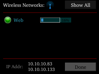
The Wireless Networks screen is displayed by touching WiFi on the System Setup screen. Available networks that have been used or previously configured are displayed in the main area of the screen. Selecting a network from the list displays network information and enables the user to connect to the network, forget the network, or cancel configuration of the network.

The wireless icon shows if the wireless feature is enabled or disabled. A red 'x' will appear through the icon if wireless is disabled. Enable/disable wireless through the System Configure Screen.
PZ5 Features
Status LED
The status LED above the touchscreen indicates the PZ5 connection and charging status.
Clip Warnings and Activity Display
The front panel LEDs can be used to indicate spike activity and/or clip warning for analog input channels. They can be configured under software control using the PZ5 gizmo in Synapse, or under manual control using the toggle switch on the PZ5 touchscreen.
LED Indicators (analog)
When enabled, LEDs for each channel are lit green to indicate activity or red to indicate a clip warning. The top row indicates the odd channels (left to right). The bottom row indicates the even channels.
 |
| Green: Activity |
 |
| Red: Clip Warning |
Note
The LED indicators are also mirrored on the RZ2 LCD display when the PZ5 is connected to the PZ Amplifier port on the back of the RZ2.
Clip Warning
Analog clipping occurs when the input signal is too large. When the input to a channel is within 3 dB of the PZ5's maximum voltage input range the LED for the corresponding channel is lit red to indicate that clipping may occur.
Activity
When configured to indicate activity, LEDs are lit green whenever a unit (spike) occurs on the corresponding channel. The sensitivity threshold for the green LED is ~200 uV.
LED Indicators (digital)
LEDs that represent digital input boards, indicate the number of input channels with each LED indicating 16 channels. For example, four LEDs indicates 64 input channels have been detected on that connection.
External Ground
The external ground is optional and should only be used in cases where the subject occasionally contacts a metal surface that isn't tied to the animal ground, such as a lever press. When contact is made, a ground loop is formed that temporarily adds extra noise to the system. Grounding this metal surface directly to the TDT hardware removes this ground loop at the cost of raising the overall noise floor a small amount.
A banana jack located on the back of the PZ5 provides connection to common ground. Any logical amplifier configured through the PZ5 touchscreen has this shorted by default. The PZ5 gizmo in Synapse allow you to float that ground connection on individual sub-amplifiers.
An external grounding cable kit is included with the PZ5. Each kit includes: one male banana plug to male banana plug pass through and one male banana plug to alligator clip pass through. These cables also include ferrite beads to remove any potential RF noise that might travel through the cable. For best results position the ferrite bead close to the source of the RF noise.
Battery Overview
The PZ5 features a 32 Amp-hour Lithium ion battery pack.
Charging the Batteries
Operate the PZ5 with the charging cable disconnected. An external battery pack (PZ-BAT) or external charger and extra battery (PZ5-BAT) is available for longer battery life and extended recording sessions. See PZ-BAT and PZ5-BAT.
PZ5 Technical Specifications
Analog Inputs
^Note: If recording at ~50 kHz on 128 channels, see PZ5 Software Control for more information.
Analog Input Sample Delay
Depends on PZ5 and RZ processor sample rates. All units in samples.
Digital Inputs
RHD2000 series amplifier boards and SPI interface cables are used in TDT's ZD and OD Intan-based digitizing headstages. They are available from Intan Technologies.
Important
The specifications below are dependent on the amplifier board. See Intan RHD2000 series website for latest, full performance specifications.
General
Input Connectors
The PZ5 has up to eight 26-pin headstage connectors (analog) or up to four 12-pin Omnetics nano connectors (digital) on the back of the unit. The connectors are labeled alphabetically from bottom to top. Each connector carries signal for one bank of channels with ground and reference. The corresponding channel numbers depend on 1) the reference mode configurations or number of channels in a connected digital amplifier board and 2) the position of the bank in a logical amplifier.
For simplicity sake, the diagrams below assume channels for that connector begin with channel 1. For example, A1 - A16 represent the 16 channels coming from the connected headstage. The user must increment the channel numbers by 16 (or 8 if in Differential mode) according to the mode and position of the connector. So, for the connector labeled 'A', A1 is channel 1 while on the connector labeled 'B', A1 may be channel 17.
Pinout Diagrams
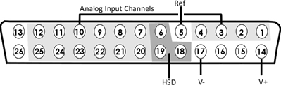
Local, None or Shared Reference Mode
^Note
In Local reference mode, Pin 13 is AltRef. Otherwise, Pin 13 is Ground.
* In Shared reference mode, only Pin 5 of the first bank of the logical amplifier is connected. It is shared internally among the other banks of the logical amplifier.
* In None reference mode, Pin 5 is not connected.
Differential Reference Mode
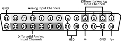
Note
There are 8 (+) channels and 8 (-) channels per DB26 connector. Subsequent banks are indexed by an additional 8 channels.
Note
See Tech Note 0896 before attempting to make any custom connections.
Digital Connectors
The digital input connector is a self-aligning 12-pin Omnetics PZN-12 polarized nano connector that mates directly to an Intan RHD2000 SPI interface cable.