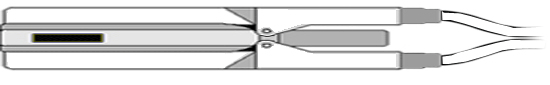
ZIF-Clip® ZD Digital Headstages
ZIF-Clip® ZD Overview
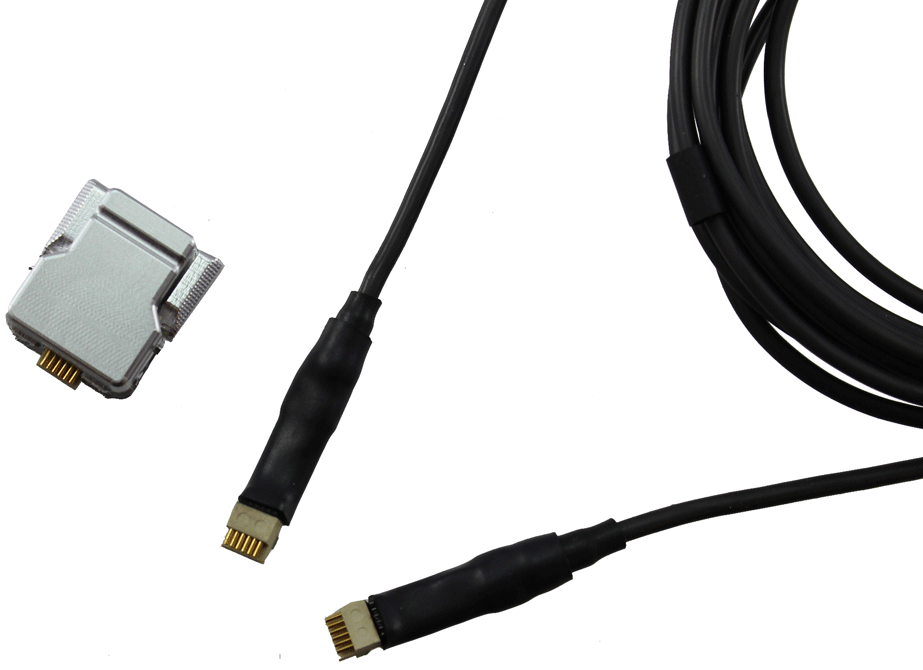
ZD ZIF-Clip® digital headstages use Intan RHD2000 amplifier chips to digitize physiological recordings directly inside the headstage. Digitized signals are routed to a PZ5 or Subject Interface (SIM) with a digital input board for transfer to an RZ base station. A single PZ5/SIM digital input board can support up to 128 channels via a direct connection to any of the ZD headstage form factors (32, 64, 96, or 128 channels). The headstage cable is detachable for easy, low-cost replacement.
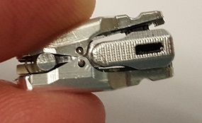
The ZIF-Clip® headstage (Patent No. 7540752) features an innovative, hinged headstage design that ensures quick, easy headstage connection with almost no insertion force applied to the subject. ZIF-Clip® headstage contacts seat inside the probe array and snap in place, firmly locking the headstage and probe with very little applied pressure. These self-aligning headstages provide long lasting low insertion performance for a variety of channel number and electrode configurations. An aluminum finish provides increased durability.
These headstages are recommended for use with probe that have an impedance in the range of 20 Kohm to 2 Mohm. By default, ground and reference are separate on all ZIF-Clip® headstages yielding a referential configuration. Reference and ground may be tied together on the headstage adapter or microwire array for single-ended configurations.
Part Numbers:
ZD32 - 32-channel Digital ZIF-Clip® headstage
ZD64 - 64-channel Digital ZIF-Clip® headstage
ZD96 - 96-channel Digital ZIF-Clip® headstage
ZD128 - 128-channel Digital ZIF-Clip® headstage
ZD-CBL - digital headstage cable
Adapter and Probe Connection
Warning
The headstage has sensitive electronics. Always ground yourself before handling.
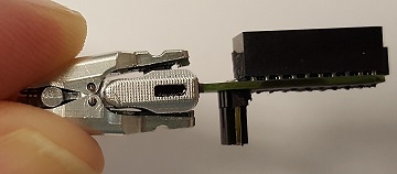
ZIF-Clip® headstages are designed to automatically position the high density connectors on the headstage and probe (or adapter).
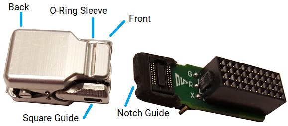 |
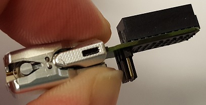
| ZIF-Clip® Connection (ZD32 headstage and ZCA-NN32 adapter) |
Connect probes and adapters to the headstage as described below.
Warning
The ZIF-Clip® headstage must be held in the fully open position while being slid into position. The headstage should only be closed when fully engaged. Sliding the headstage into position while applying pressure to the tip will permanently damage the ZIF-Clip® headstage and micro connectors.
ZIF-Clip® Headstage O-Rings
All ZIF-Clip® headstages are shipped with two o-rings for additional connection security. Gently slip the o-ring onto the headstage sleeve and then roll the o-ring towards the back of the headstage. Connect the probe or adapter to the headstage as described above. Once the connection is secure, roll the o-ring forward until it settles into the sleeve on the front of the headstage.
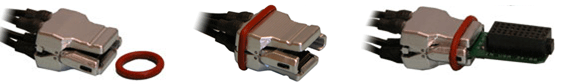 |
| O-Ring Use and Positioning |
ZIF-Clip® Digital Headstages PZ5/SIM Connection
The ZD ZIF-Clip® digital headstage uses a single detachable SPI Interface Cable that transmits all channels to a digital input board, housed in a PZ5 or SIM. The PZ5/SIM will automatically detect the number of channels in the headstage. If more than one headstage is used, all channels will be concatenated together, starting with connector "-A-", to create the output signal to the RZ base station. The total channel count of all connected headstages cannot exceed the maximum channel count for the PZ5/SIM. See PZ5 NeuroDigitizer or SIM Subject Interface for more information.
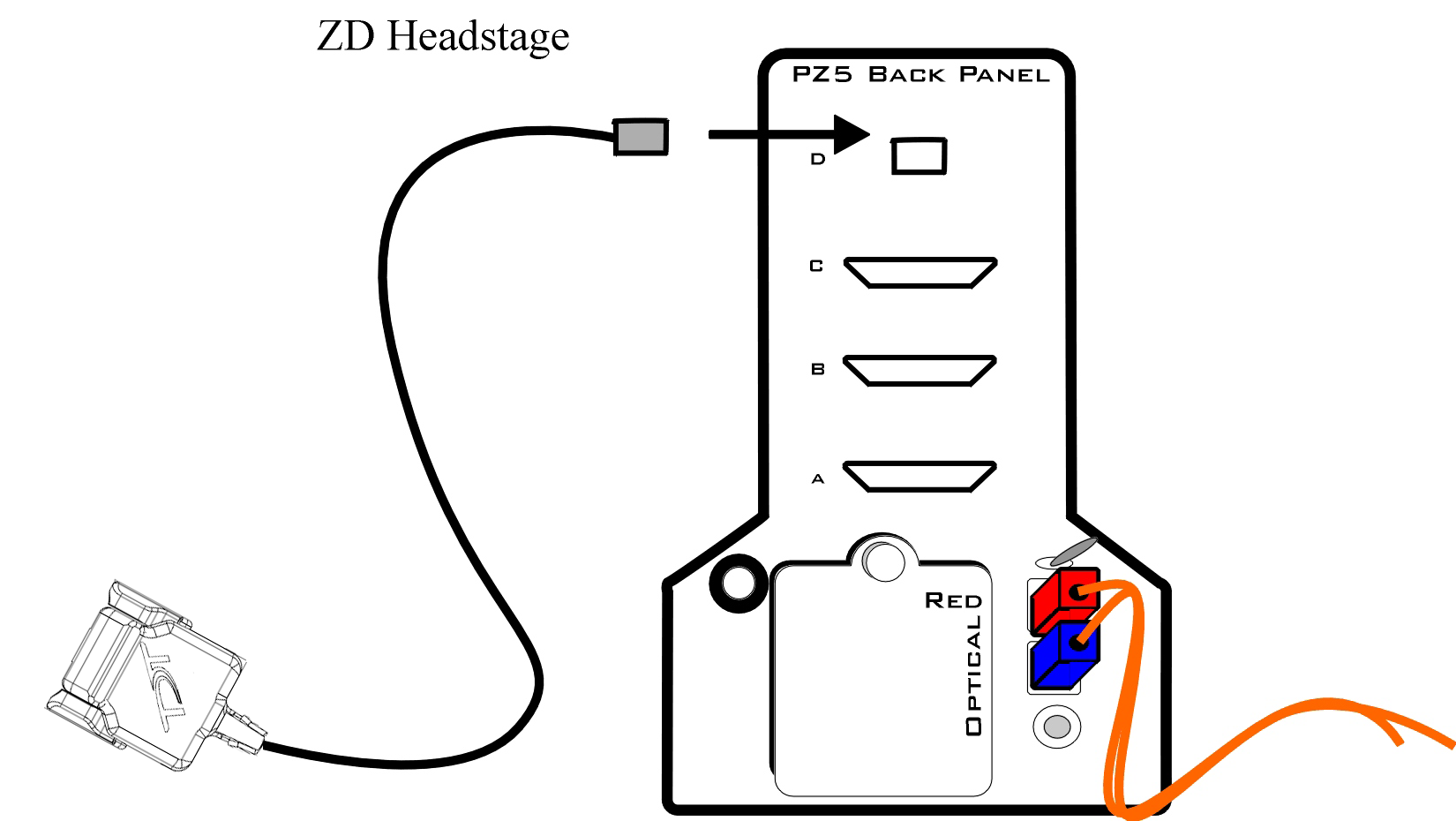 |
| ZIF-Clip® ZD Digital Headstage to Preamplifier Connection Diagram |
ZIF-Clip® Digital Headstage Technical Specifications
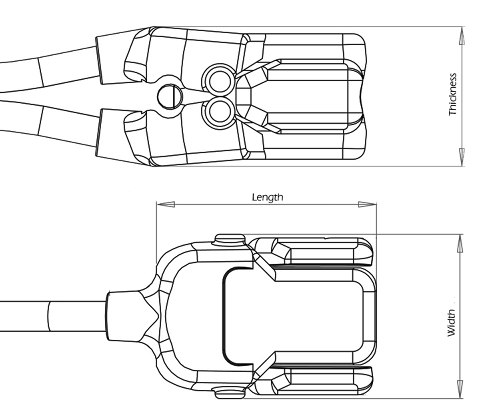
Dimensions
Important
When using multiple headstages, ensure that a single ground is used for all headstages. This will avoid unnecessary noise contamination in recordings. See the Headstage Connection Guide for more information.
ZIF-Clip® Headstage Pinouts
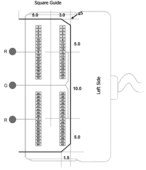
If you are interested in using a third party electrode see ZIF-Clip® Headstage Adapters. If there is no adapter offered for the desired electrode, the following diagrams show the headstage pinouts (channel connections to the amplifier) and board dimensions for connectors to match ZIF-Clip® headstages. A black square guide is used to align the headstage to ZIF-Clip® compatible connectors and can be used in the diagrams below to orient "left" and "right" sides of the headstage shell.
For Synapse users, use the Channel Mapper gizmo to reorder the channels according to the pinouts below. Choose TDT > HEADSTAGE > then the ZDn that matches your headstage.
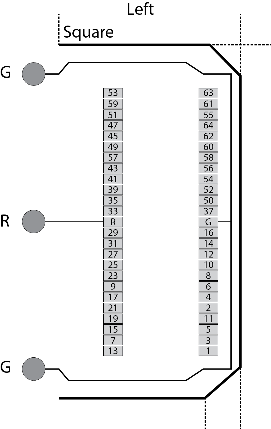
16- and 32-Channel Headstage Pinouts
Images are not to scale. Pinouts are looking through the headstage shell (or into a matching board connector). All board dimensions are in millimeters and are identical for both sides, board thickness is 0.75 mm, and connectors are centered as shown.
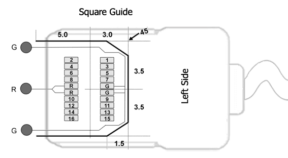
G Common/Ground Connection
R Reference Connection
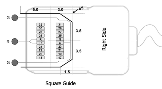
Hirose Connectors:
ZD16 - DF30FC-20DS-0.4V x 1
ZD32 - DF30FC-20DS-0.4V x 2
64-Channel Headstage Pinouts
Images are not to scale. Pinouts are looking through the headstage shell (or into a matching board connector). All board dimensions are in millimeters and are identical for both sides, board thickness is 0.75 mm, and connectors are centered as shown.
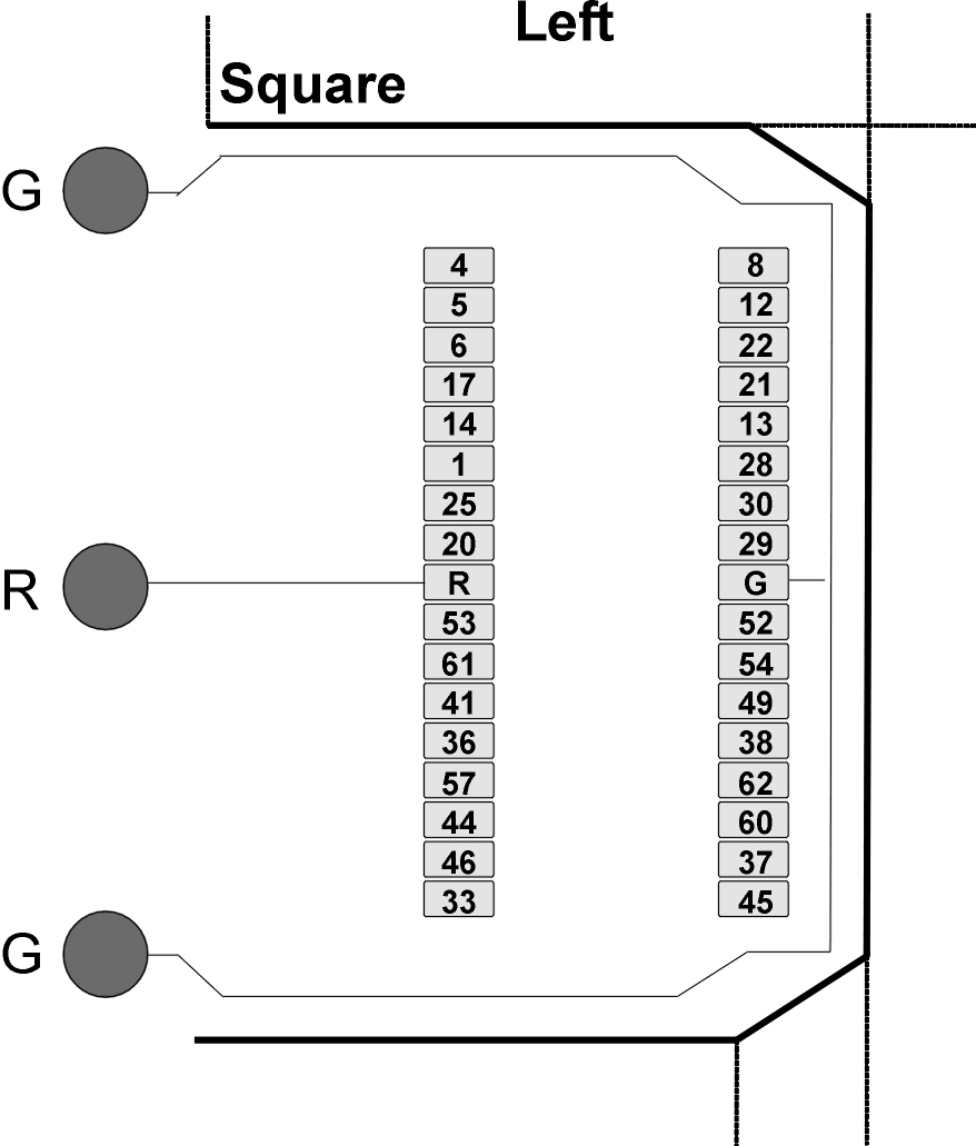
G Common/Ground Connection
R Reference Connection
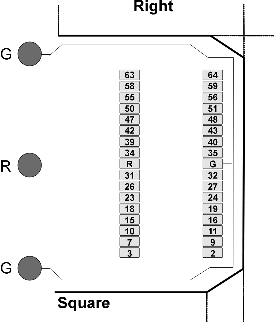
See Hirose specification for recommended footprint.
Hirose Connectors:
ZD64 - DF30FC-34DS-0.4V x 2
96-Channel Headstage Pinouts
Images are not to scale. Pinouts are looking through the headstage shell (or into a matching board connector). All board dimensions are in millimeters and are identical for both sides, board thickness is 0.75 mm, and connectors are centered as shown.
G Common/Ground Connection
R Reference Connection
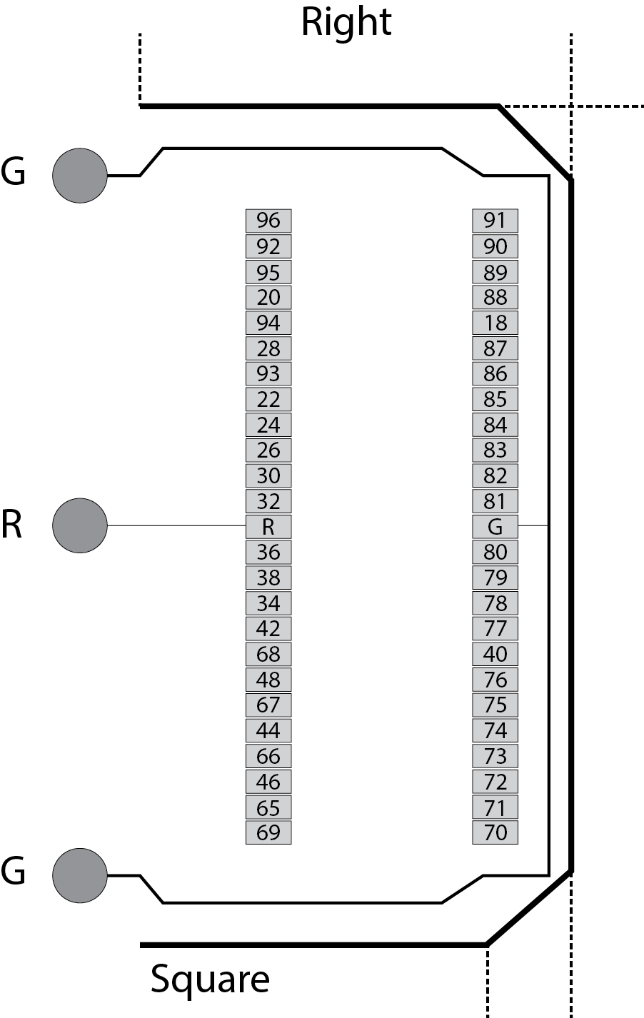
See Hirose specification for recommended footprint.
Hirose Connectors:
ZD96 - DF30FC-50DS-0.4V x 2
128-Channel Headstage Pinouts
Images are not to scale. Pinouts are looking through the headstage shell (or into a matching board connector). All board dimensions are in millimeters and are identical for both sides, board thickness is 0.75 mm, and connectors are centered as shown.
G Common/Ground Connection
R Reference Connection
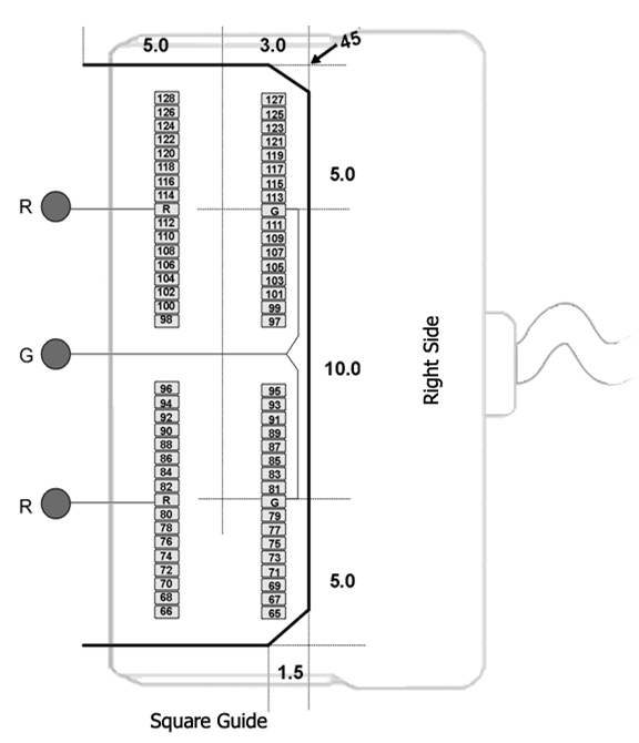
See Hirose specification for recommended footprint.
Hirose Connectors:
ZD128 - DF30FC-34DS-0.4V x 4