Unary Signal Processor
Common Use Cases

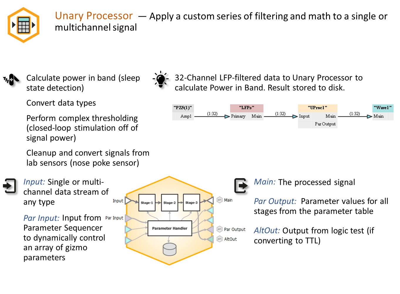
Implement series of mathematical operations to incoming signals. Use this gizmo to perform interesting signal processing on incoming data, such as power in band, RMS, or scaling. Can also perform complex thresholding or type conversion on signals.
Gizmo Help Slides

Reference
The Unary Signal Processor gizmo applies a series of mathematical operations to a single or multi-channel signal. Operations such as RMS and power band calculations are available as presets. Other available operations include adding custom FIR or IIR filters, calculating absolute value, converting data types, and many others, all in one gizmo. Example uses include triggering based on power in a frequency band, or processing/converting external sensor voltages.
The gizmo uses a bounded parameter table (see Using Parameters) to define values for some operations, such as filter settings and scale/shift parameters. Optionally, you can enable runtime control or storage of these gizmo parameters.
The Runtime Interface
Runtime Plot
This gizmo is not specifically associated with any plotting, other than optionally storing parameter values when they change, which is not typical. If you want to view the output data during an experiment, you can add a Stream Data Storage gizmo to the output.
Runtime Parameter Controls
The gizmo parameters will be shown at runtime. You can enable runtime control of any parameter by selecting Widget in the parameter table. See Using Parameters for more information.
Unary Signal Processor Configuration Options
 |
| Options Area |
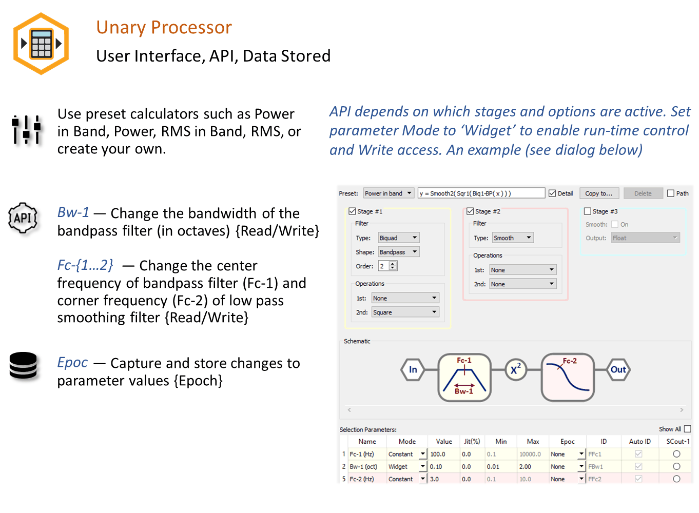
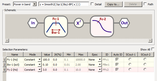
The Unary Options area displays the mathematical formula, an image showing the operations and parameters used by each operations, and the corresponding editable parameters. You can choose a "Preset" formula, such as RMS or Power In Band, or create your own. By default, the formula is set to Bypass (output = input).
The gizmo unary formula consists of up to three stages. If you want to view or customize the stages, select the Detail check box. The stages are numbered to reflect the order of operations and you can click or clear the check box for each stage to enable or disable it.
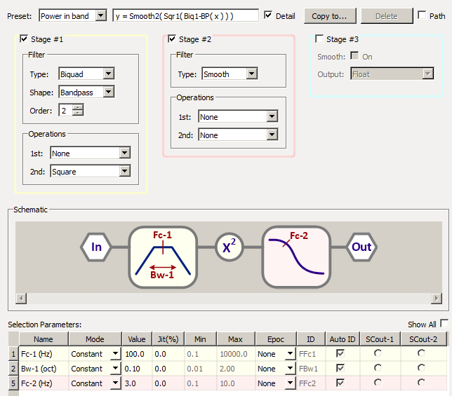 |
| Unary Options Area - Detail View |
As stages are enabled or modified the parameter table is updated to show the updated parameters in use. See Using Bounded Parameters for more information on using the table.
When you are happy with a modified formula you can use the Copy to button to save it for later use. The name you choose will then appear in the Preset list. This also ensures the formula is included with all files, if you ever wish to export or share the experiment. To show the path where Presets are stored, click the Path check box.
Stage 1 and 2
Each of these stages provide a filter and two operations.
Stage 3
This stage provides an exponential smoothing filter and a way to change the data type. The Fc-3 parameter determines the effective low pass corner frequency of the filter.
Integer
Scales the input by the OpParA-3 parameter and then converts to an integer.
Logic
The operations available use natural language labels and apply a truth test using editable values in the parameter table for comparison. The operation outputs a "1" if true or a "0" if false.
Select Logic Out to Alternate if you wish to have both the logic output and the signal before the logic test available as outputs to the gizmo. For example, if making an RMS threshold detector, you can output both the threshold crossings and the RMS value used for the detection for visualization with other gizmos. In this case, the Main output will be the RMS signal and the AltOut output will be the logic signal.
Working with Single and Multi-Channel Signals
The gizmo can be used with single or multichannel signals and automatically detects the number of channels in the input signal. The formula is applied independently to each channel. The Unary Signal Processing gizmo can handle up to 96 channels. If more channels are required, use a second gizmo and a Signal Merger gizmo to combine the results back into one processing stream.
Tip
To pick one channel for processing from a multichannel signal, use the Selector gizmo