Timer
Common Use Cases

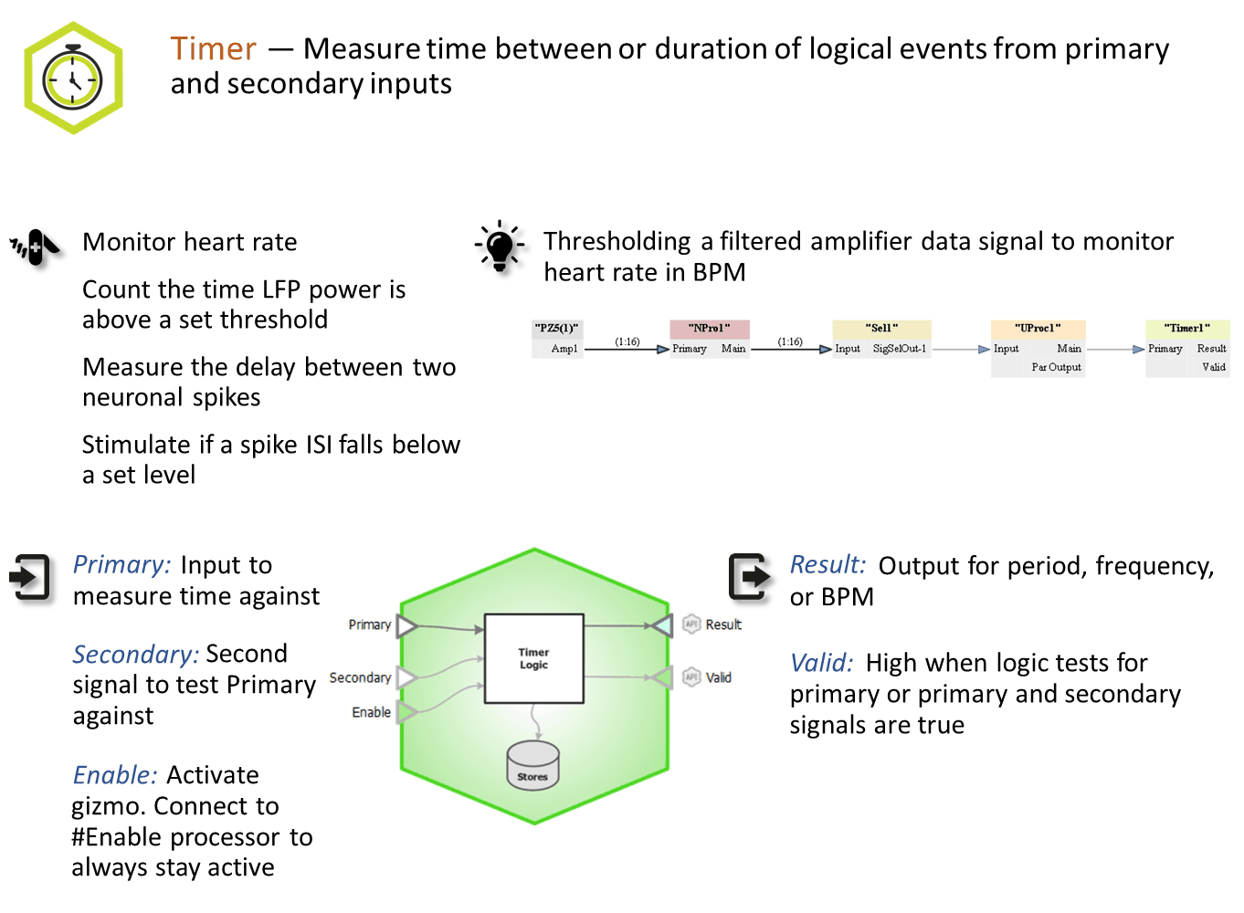
Measures time between or duration of logical events from primary and secondary inputs. Use this gizmo to calculate event frequency or time logical events. Can be used to measure response time to stimuli, calculate heart rate, and time other physiologic intervals
Gizmo Help Slides
Reference
The Timer gizmo accepts all single channel signal types. The input first passes through a truth test. For a logic signal, this is simply a true/false test. If an integer or floating point input is used, the test can be that the signal is above/below a certain threshold, or inside/outside a range of values.
The Runtime Interface
Runtime Plot
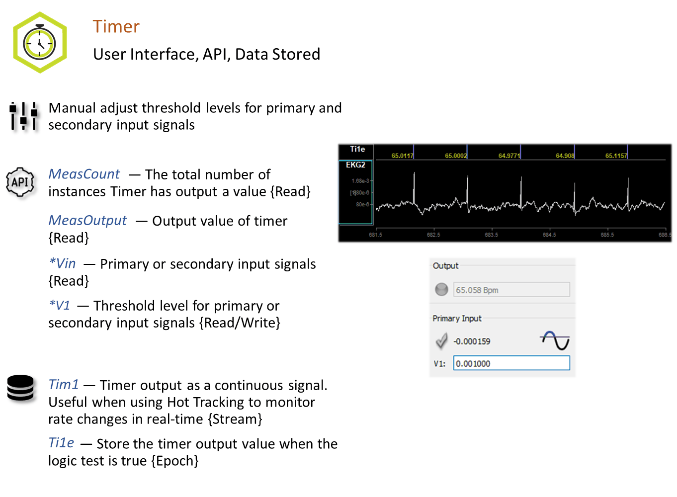
At runtime, the standard Synapse data plot displays any stored data. The timer can save timestamped epoch events when the measurements are taken, and/or a continuous stream of the measurement results.
Timer Tab
The runtime interface must be enabled in the General Tab before it can be used.
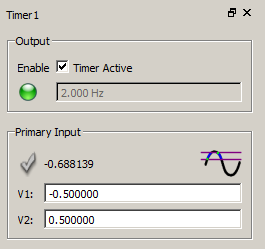
If a signal input is integer or floating point type, the values used for the truth test are adjustable at runtime.
If Enable Control is turned on, a check box on the UI shows if the timer is enabled or not.
 |
| Timer Runtime UI |
In the above example, the Enable Control option is set to 'Manual/API'. The input signal is floating point with the truth test set to 'Between'. The signal will be true if it is between -0.5 and 0.5.
The value in the Output box is the most recent measurement. The green LED is active to indicate that a measurement recently took place.
The check mark for Primary Input is not lit because the test condition is not met; the current signal value is outside the bounds.
Timer Configuration Options
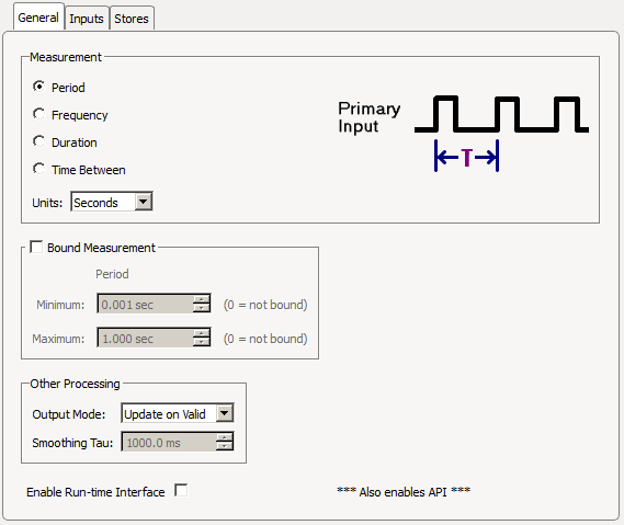
General Tab
 |
| General Tab |
Measurement
Choose which measurement to make and the output units. The smallest possible measurement is two samples of the system clock.
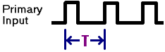
Period measures the time between consecutive onsets of the primary input signal
in units of seconds, milliseconds, microseconds, or samples.
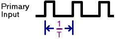
Frequency measures the frequency of consecutive onsets of the primary input
signal in units of hertz, kilohertz, or beats per minute (BPM).
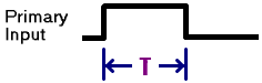
Duration measures the time between the onset and offset of the primary input
signal in units of seconds, milliseconds, microseconds, or samples.
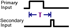
Time Between measures the time between the onset of the primary input signal
and the onset of the secondary input signal in units of seconds, milliseconds,
microseconds, or samples.
Bound Measurement
If Bound Measurement is enabled, the calculated measurement result will never be outside of the chosen minimum and maximum values.
In Period or Frequency measurement mode, if the measurement is outside of the limits, it will clamp to the nearest limit.
In Duration measurement mode, if the maximum bound is exceeded or the minimum bound isn't met, then this will not count and a measurement will not be made.
In Time Between measurement mode, when bounding is used the primary input is ignored when the timer is running and less than the minimum bound, so it can't re-trigger. Also, the secondary input is ignored before the minimum bound is reached and after the maximum bound is reached, so valid measurements are only taken in between the given bounds.
Other Processing
Output Mode controls how the measurement signal (Result) is handled.
Update On Valid means the Result is latched when the measurement occurs and Result holds that value until the next measurement is made.
Smoothed behaves like Update On Valid but also applies an exponential smoothing filter with the desired Smoothing Tau. The larger the Smoothing Tau, the smoother the Result signal.
Hot Tracking provides a more instantaneous approximation of the Result while the measurement is occurring. This is useful for tracking irregular waveforms like spike firing rate.
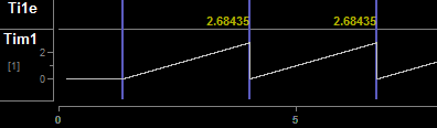
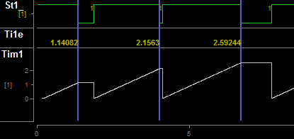
For Period measurements, the Result resets to 0 when a new Primary Input onset
occurs and rises linearly until the next Primary Input onset, at which point a
measurement is taken and it resets again.
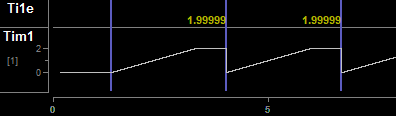
If the maximum bound is reached, Result latches at the maximum bound value until
the next onset/measurement.
If the minimum bound is greater than zero, the Result will reset to this value
(instead of 0) and will stay there until enough time has elapsed to meet the
minimum bound requirement, and will then rise linearly until the next onset (or
the maximum bound is reached).
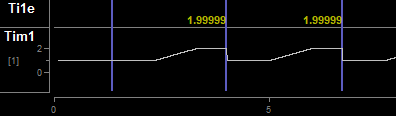
For Frequency measurements, the Result value latches until enough time has
elapsed between onsets such that the next frequency measurement must be lower
than the previous Result, at which point the Result begins decreasing in real-
time until the next onset occurs (or the minimum bound is reached) and latches
the new measurement value. If the frequency between onsets increases, the Result
will immediately increase to the new value.
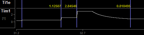
For Duration, the Result resets to 0 when an onset occurs and rises linearly
until the offset occurs, or until the maximum bound is reached, and latches this
value until the next onset.
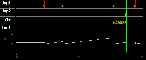
For Time Between, the output resets to 0 when the Primary Input onset occurs
and rises linearly until the Secondary Input offsets occurs, or until the
maximum bound is reached, and latches this value until the next Primary Input
onset.
Inputs Tab
Select the truth tests for the input signal(s) and determine when to activate the timer processing and storage.
 |
| Inputs Tab |
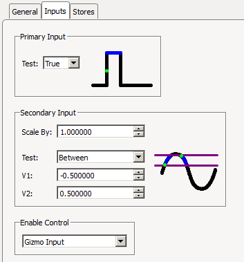
Primary Input
If the primary input is a Logic signal, the test can either be True or False. If the primary input is an Integer or Floating Point signal, the input can first be scaled and then a threshold Test is applied. For Above and Below, V1 is the only value shown and used for the threshold test. For Between and Outside, V1 is the minimum bound and V2 is the maximum bound.
Secondary Input
The Secondary Input is only visible if the Measurement type is Time Between. This contains the same truth test options as the Primary Input above.
Enable Control
'None' means the timer is always active.
'Gizmo Input' means the timer is only active when an additional gizmo input signal (a Logic signal called 'Enable') is True.
'Manual/API' enables user control of timer processing. Note that this is only available if the Run-Time Interface is Enabled on the Misc Tab.
Stores Tab
Choose what data (if any) to store.
 |
| Stores Tab |
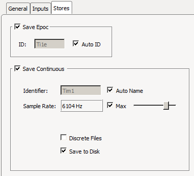
Save Epoc
Store the timestamp and Result when Valid is true (when a measurement is taken).
Save Continuous
Saves the Result continuously and makes it visible on the runtime Data Plot.