MRI Recording Processor
Common Use Cases

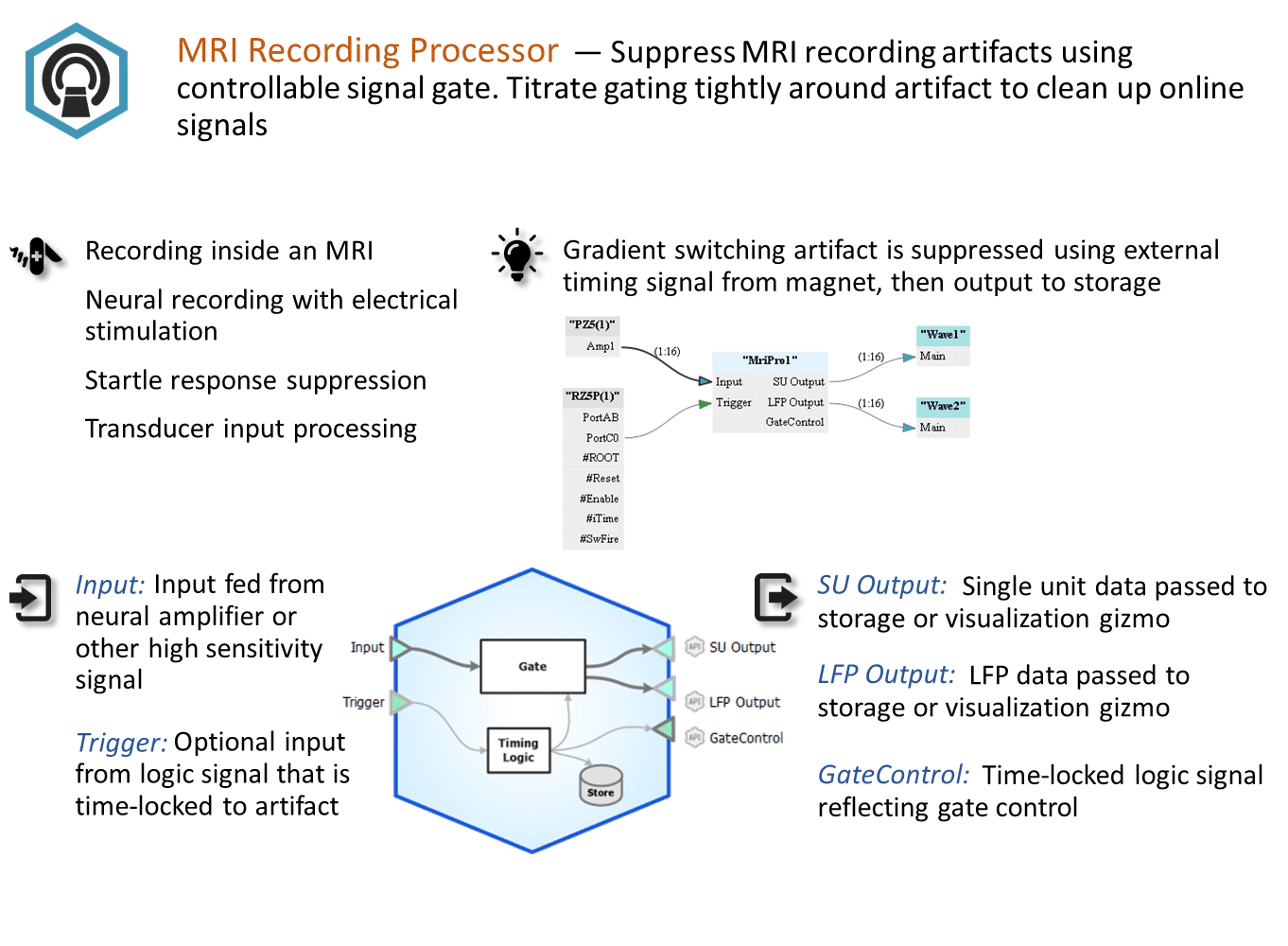
Suppress MRI recording artifacts using controllable signal gate. Titrate gating tightly around artifact to clean up online signals. Use this gizmo to eliminate gradient switching artifact in an MRI recording environment. Can automatically detect artifacts or be triggered using timing signal from the magnet.
Gizmo Help Slides
Reference
The MRI Recording Processor gizmo removes MRI scanner artifacts from Single Unit and LFP data in real time. It can automatically detect/reject artifacts in the data stream or be synchronized with an external TTL. Timing logic can also be stored.
Typically the input is the raw amplifier signals and the output Single Unit data is ready for online spike sorting gizmos.
The MRI Recording Processor Runtime Interface
Runtime Plot
If you choose to save gate timing, a plot showing the timing of the gate is added to the runtime window for visualization.
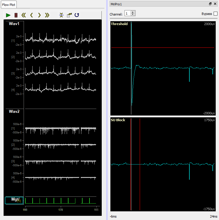 |
| Runtime Plots include MRI Artifact Timing |
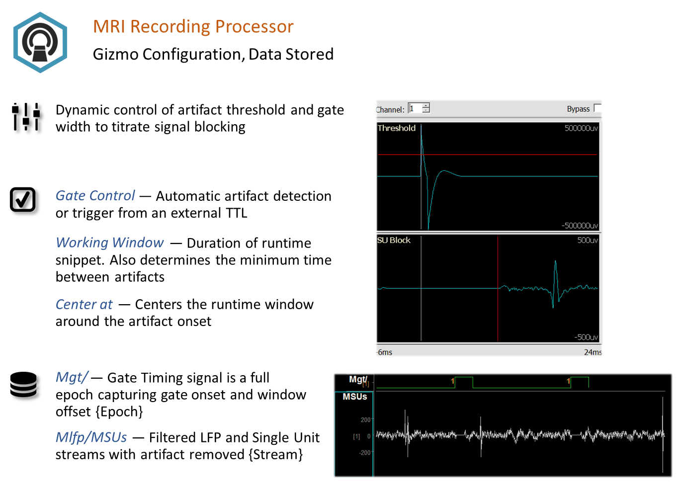
The threshold plot lets you choose a threshold for automatic artifact detection/rejection. To adjust the y-scale, use the mouse wheel or Shift + Left-click drag the mouse. Right-click the choose Find Threshold to determine a reasonable threshold before fine tuning.
The lower plots (SU Block and LFP Block, if enabled) let you set a blanking window around the artifact onset. Adjust the left and right vertical bars to create as small a blanking window as possible while still removing the artifact. Click the Bypass checkbox to see what the waveform looks like without the rejection applied.
In the Flow Plot above, Wav1 is the raw signal going into the blocker with a >2 mV artifact, and Wav2 is the output of the single unit data with artifacts removed so you can see the spike waveforms are still present but without the large artifact.
The timing signal of the rejection window is shown at the bottom in green.
MRI Recording Processor Configuration Options
 |
| Trigger and Storage Options |
General
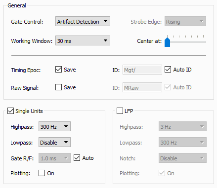
The Gate Control can trigger off a user-defined threshold crossing at runtime. If the artifact is timed to another gizmo or an external TTL event, those can be used as the gate trigger instead.
Working Window determines what size of snippet to show in the runtime plots for gate control, and also determines the minimum time between consecutive artifact detections. If you find that multiple artifacts occur in the same window, consider reducing the working window size.
Center at determines where to position the artifact onset in the runtime plots.
Important
The MRI processor operates on a delayed version of the waveform so it can effectively remove the artifact. The Center At slider ranges from 20% to 80% of the working window, so with Center At at the far left slider position you should see ~20 ms delay when Working Window is 100 ms.
Setting the Working Window smaller will decrease your signal delay, but this will only work if your artifact is shorter than the Working Window.
Timing Epoc stores the rejection timing signal in the data tank.
Raw Signal stores the raw streaming data before the rejection is applied.
Single Units
Set the filter characteristics for the Single Units signals before artifact rejection.
The Single Unit artifact blocker uses a cosine-squared gate. The rise/fall time (Gate R/F) represents the amount of time it takes to reduce the signal by 90%, and to increase it back to 90% of its final value. When set to Auto it automatically adjusts based on the Working Window size.
Plotting adds the resulting stream to the Flow Plot.
LFP
Set the filter characteristics for the LFP signals before artifact rejection.
The LFP artifact blocker uses a custom rejection method to reduce effects after gating.
Plotting adds the resulting stream to the Flow Plot.