FB128 Neural Simulator
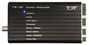
Overview
The FB128 Neural Simulator is a tool for testing experimental paradigms during the design phase and debugging problems when they arise. The compact, battery operated device simulates neurological waveforms or sine waves that can be output directly to a ZIF-Clip headstage. The FB128-OMN version includes connections for a 16 channel and 32 channel Omnetics headstage as well.
Neurological simulations consist of an LFP component and spike components. Eight unique spike waveform shapes are used depending on the mode. Up to 128 channels can be output (up to 96 unique).
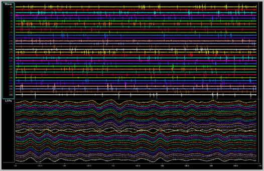 |
| 32 channels from FB128 - filtered for Spike (top) and LFP (bottom) waveforms |
The simulator can operate in eight different modes and includes an inhibitory/excitatory option for even more output variations. The simulation modes are listed on the face of the module and LEDs indicate which is active. Operational buttons or switches, a TTL input, and a charger input are positioned on one end of the module and output connectors for headstage connection are positioned on the other.
Hardware Set-up
When using the FB128 to test your protocol or recording hardware, set-up the recording part of your system as you would during your experiment with the FB128 in place of the subject and electrodes.
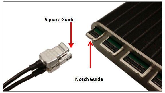
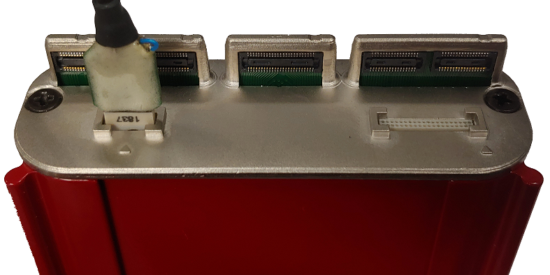
ZIF Connectors
Four output connectors are positioned side-by-side at one end of the simulator. One for each size of ZIF-Clip headstages, including one connector for the ZC16/ZC32/ZD32 and one each for the ZC64/ZD64, ZC96/ZD96, and ZC128/ZD128.
Connect the headstage to the appropriate connector just as you would connect it to an electrode or adapter. First, line up the square guide on the headstage with the notch on the probe connector. Hold it firmly open at the wire end of the connector until it is fully in position then clamp it firmly in place.
 |
| ZC32 and FB128 |
Caution
Failure to hold the clip open until it is fully in position can cause damage to the headstage connectors.
Omnetics Connectors
The FB128-OMN has 16- and 32-channel Omnetics connectors for LP16CH-Z and LP32CH-Z style headstages.
Connect the headstage to the appropriate connector just as you would connect it to an electrode or adapter. Line up the label on the Omnetics connector on the headstage with the arrow on the probe connector.
 |
| LP16CH-Z and FB128-OMN |
Simulation Modes
The Mode button, is positioned on the end opposite the output connectors.
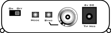
To cycle through the operating modes:
- Briefly press the Mode button. The active mode is indicated by a lit LED on the face of the module. If you press too long and the LED is blinking, you are in Channel Mapping Mode. See Channel Mapping Mode.
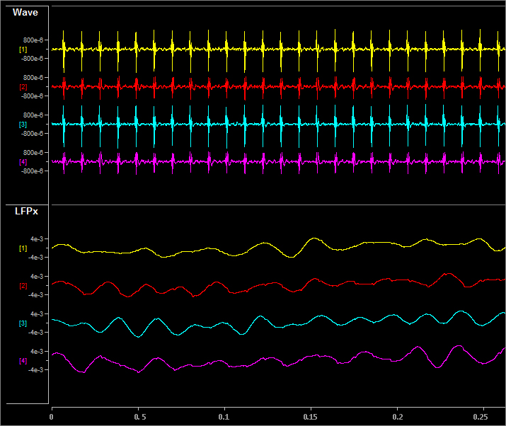
NORMAL
Neurological waveforms, including spike waveforms and LFP.
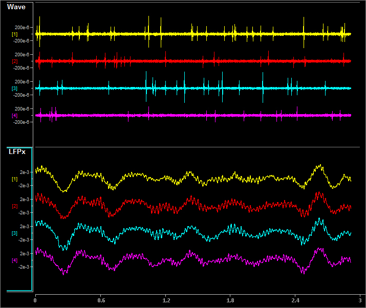
Pictured waveforms were generated by the FB128 and plotted in Synapse with the following settings:
Wave Filter Settings: High Pass: 300 Hz, Low Pass: 5000 Hz
LFPx Filter Settings: High Pass: 0 Hz, Low Pass: 300 Hz
HASH
NORMAL mode but with spikes scaled down by a factor of 2.
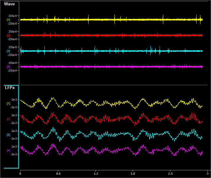
Pictured waveforms were generated by the FB128 and plotted in Synapse with the following settings:
Wave Filter Settings: High Pass: 300 Hz, Low Pass: 5000 Hz
LFPx Filter Settings: High Pass: 0 Hz, Low Pass: 300 Hz
LFP ONLY
NORMAL with spikes scaled to zero.
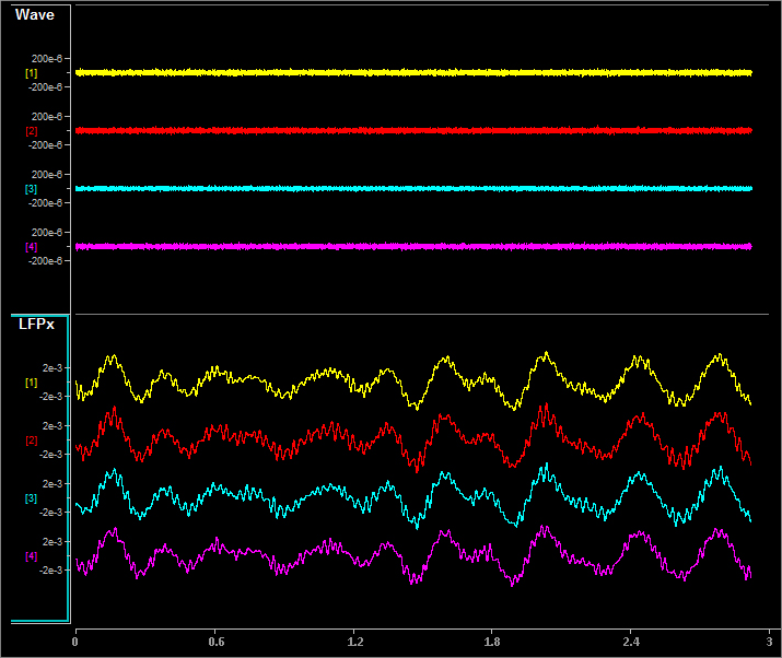
Pictured waveforms were generated by the FB128 and plotted in Synapse with the following settings:
Wave Filter Settings: High Pass: 300 Hz, Low Pass: 5000 Hz
LFPx Filter Settings: High Pass: 0 Hz, Low Pass: 300 Hz
TETRODE
Neurological LFP waveforms with spikes--where spikes on each group of four channels fire synchronously. Channels 1-4 fire together, channels 5-8 fire together, and so forth.
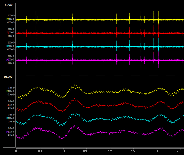
Shown: Tetrode + Excitatory Mode
Pictured waveforms were generated by the FB128 and plotted in Synapse with the following settings:
SUwv Filter Settings: High Pass: 300 Hz, Low Pass: 5000 Hz
RAWx Filter Settings: Unfiltered
Important
To better view Tetrode mode (as pictured above) the channels must be re-mapped.
For Synapse users, use the Channel Mapper gizmo. Choose TDT > Electrode > then FBnTET to match your channel count.
For RPvdsEx / OpenEx users, the map for each ZIF-Clip headstage is included in FB128Tetrode.rcx, which is bundled in the RPvdsEx zipped examples on the TDT Website at: https://www.tdt.com/files/examples/RPvdsExExamples.zip.
SYNC 100 Hz
Neurological LFP waveforms with spikes on all channels firing synchronously at 100 Hz fixed rate. The spikes in this mode are always the same shape.
Pictured waveforms were generated by the FB128 and plotted in Synapse with the following settings:
Wave Filter Settings: High Pass: 300 Hz, Low Pass: 5000 Hz
LFPx Filter Settings: High Pass: 0 Hz, Low Pass: 300 Hz
TONE 30 Hz
30 Hz sine wave at approximately ±700 uV on all channels.
TONE 1000 Hz
1000 Hz sine wave at approximately ±70 uV on all channels (actual frequency is ~763 Hz).
TONE REF
100 Hz sine wave at approximately ±700 uV on Reference channel only. All other channels output 0. Because the reference is subtracted from all channels, the sine wave should be visible on all channels.
Note
Reference lines are connected to Ground (0 V) for all modes except TONE REF.
Inhibitory/Excitatory Mode
An inhibitory/excitatory mode can be used in conjunction with all spike modes (NORMAL, HASH, TETRODE, and SYNC 100 Hz). When enabled, the base neurological waveforms (LFP) remain the same but some spike shapes are inhibited (fire less often) while others are excited (fire more often).
The Inhibitory/Excitatory mode can be activated by holding down the Sync button or it can be controlled programmatically by sending a TTL high to the Sync BNC connector. When using the Sync input, the mode change can also be timestamped in Synapse, which is helpful when testing event-related spike changes and verifying that histogram plots are working correctly.
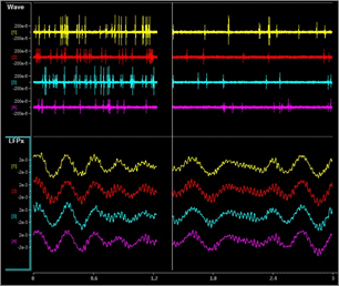 |
| Normal + Excitatory Mode vs Normal Mode |
Pictured waveforms were generated by the FB128 and plotted in Synapse with the following settings:
Wave Filter Settings: High Pass: 300 Hz, Low Pass: 5000 Hz
LFPx Filter Settings: High Pass: 0 Hz, Low Pass: 300 Hz
Channel Mapping Mode
Starting with serial number 2000, the FB128 includes a diagnostic mode that presents a unique waveform on every channel. This is useful for mapping channels or for detecting shorts on the headstage.
Press and hold the MODE button on the FB128 until the LED starts flashing, which indicates the FB128 is in channel mapping mode. Each channel plays a frequency encoded waveform that creates a unique binary pattern that can be mapped to channel number. See the image below.
Briefly press the MODE button again to cycle through the available channel count options until it matches the headstage you are testing.
* If using a ZIF headstage with a ZCA-OMN adapter, use the Mapper gizmo in Synapse and select the appropriate Omnetics adapter from the "TDT" category of maps.
Power cycle the FB128 to exit Channel Mapping Mode.
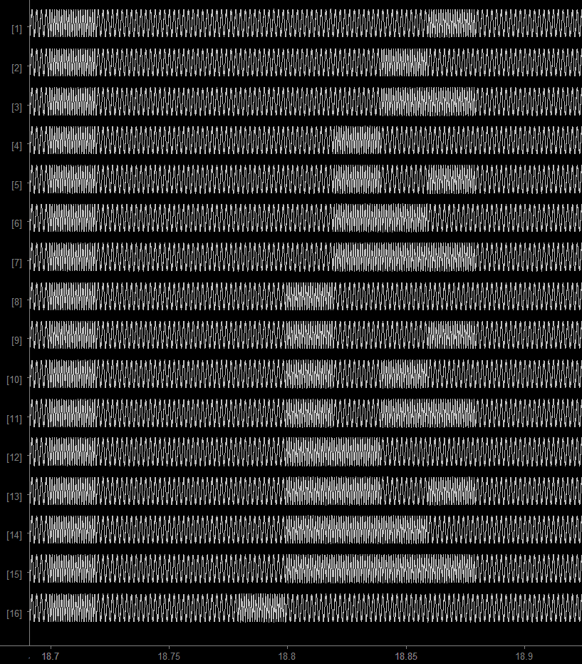 |
| FB128 Channel Mapping Mode Output |
Power
The FB128 is powered by a 1950 mAh battery with a 10-hr life. A 6 Volt charger (tip negative) is supplied for charging.