Using a Switching Headstage
The TDT switching headstage lets you stimulate and record from the same electrodes. It has one ZIF clip® connection to the subject and connects to IZV and PZA boards on a Subject Interface. The switching headstage comes in one of the configurations below.
Important
* Recall that each stimulator bank provides up to 4 independent stim channels (voices) on any given sample. These can be switched to any of the electrode channels. With the SI-MUX4 adapter from TDT you can connect four banks of stimulation to a single 16 channel electrode. With four stim banks you can stimulate all 16 channels of a ZC16_SW4 simultaneously. With the SI-MUX2 adapter and two stim banks you can stimulate up to 8 channels simultaneously.
Caution
The switching headstage only supports up to ±15 V per channel and can NOT be used in Serial Output Mode.
Software Configuration
IZV Configuration
The IZV sends control signals to the switching headstage to tell each channel whether it is connected to the stimulator or the recording banks. To enable switching headstage control, simply check Switching Headstage in the IZV Configuration options.
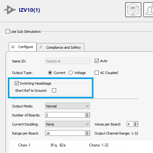 |
| IZV Configuration |
If the electrode has a reference electrode, you may want to short reference to ground in the headstage to help with stimulation artifacts.
Important
All banks of the switching headstage must be assigned to one sub stimulator. The control signals are sent through the first stim DB26 connector on the switching headstage. The switching headstage channels can not be spread across multiple IZV sub stimulators.
Electrical Stim Driver Configuration
By default, all channels on the switching headstage are in record mode. Recall from The Stimulator System that the input signal to the IZV gizmo includes both the voices and the channel numbers. The IZV will only send new commands to change the channel switches when a channel number input signal changes.
Important
All of the inter-pulse and inter-stim actions defined in the The Stimulator System, except for 'Channel Release', will keep the selected channel connected to the stimulator.
The switching time is 1 + N samples, where N is the number of stim banks. For example, an ZC32_SW8 headstage with 2 stim banks takes 3 samples to switch its channels to a new configuration. Since the switching time is not instantaneous, the channel information has to come before the stimulation waveforms begin. To do this, set the Padding parameter in the Electrical Stim Driver gizmo to the correct value.
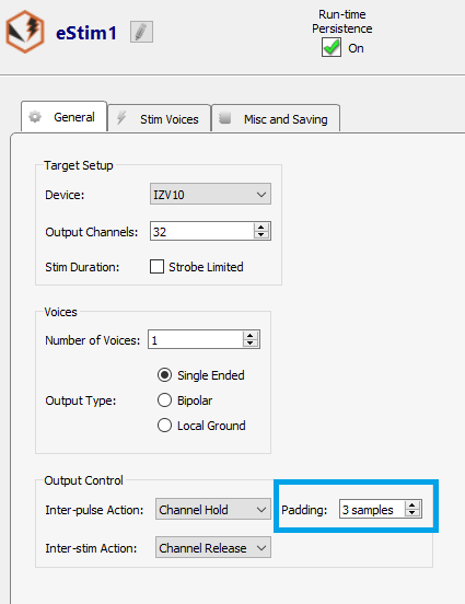 |
| Electrical Stim Driver gizmo configuration |
Note
If you are not using the Electrical Stim Driver to generate stimulus waveforms for the switching headstage then you must account for this delay in your custom gizmo.