The Stimulator System
The stimulator system consists of an RZ real-time processor with a DSP that connects to a Subject Interface via fiber optic cable. The Subject Interface supports three different kinds of boards, PZA for analog recording, PZD for digital recording, and IZV for electrical stimulation. Each Subject Interface can have up to 8 boards. The IZV can deliver arbitrary electrical stimulation waveforms of up to 20 kHz bandwidth (depending on the RZ processor sampling rate) through a passive or switching headstage.
IZV Circuit Detail
Each IZV bank has four unique hardware "voices" that can be sent to any of its 16 channels, so four independent channels can stimulate on any given sample of the real-time clock on each bank. You can assign multiple voices to the same channel to increase maximum current for one or two channels at a time.
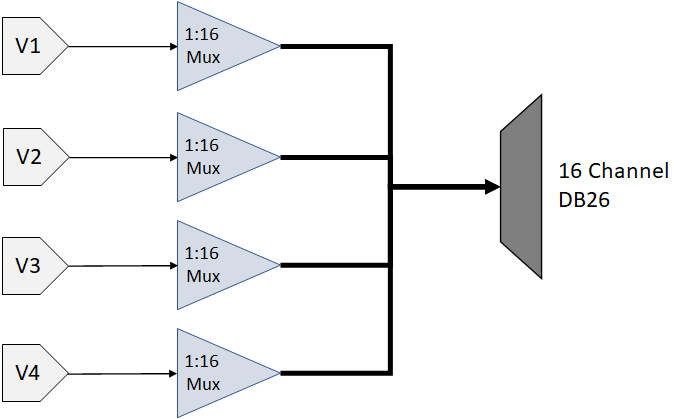 |
| IZV Bank Voices |
Each voice starts with a low voltage waveforms from the D/A converters. This is converted to constant voltage or constant current waveforms. An optional DC Block (RC circuit) removes any constant DC current from the output. You can also switch passive discharge shunts to removes excess voltage in between stim pulses.
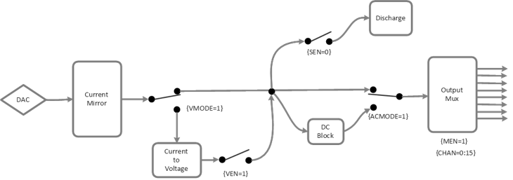 |
| IZV Voice Detail |
The signal path switches can be flipped on each sample of the real-time processor controlling the IZV. The Electrical Stim Driver gizmo in Synapse is typically used to send the control signals to the IZV gizmo. The Electrical Stim Driver controls what happens between pulses in a burst (Inter-Pulse Action) and between bursts (Inter-Stim Action). The four options are described below.
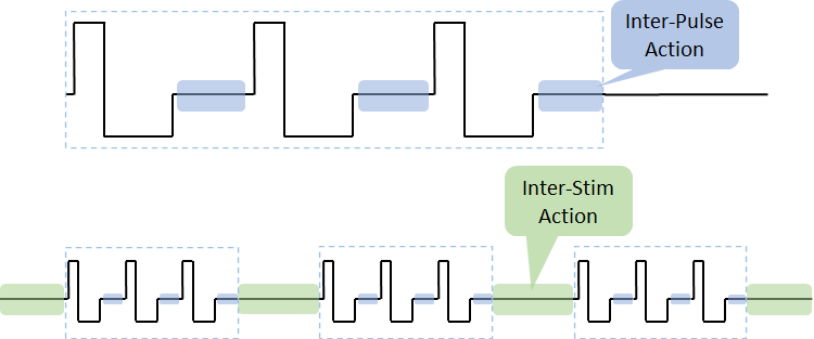 |
| IZV Inter-Stim and Inter-Pulse time periods |
Channel Release minimizes any potential charge collection in between bursts, but switching it in between short pulses is not recommended. Therefore the default configuration is Channel Hold for the Inter-Pulse Action and Channel Release for the Inter-Stim Action.
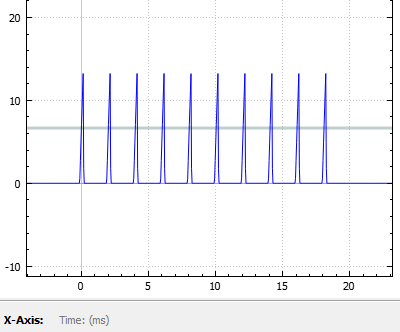
One common use case is DBS where two electrodes use a 'local ground'; essentially the second channel acts as the return path. You might see charge build up on the electrodes and not get the desired waveform. The output voltage might look something like this:
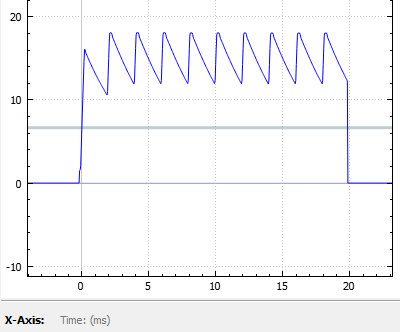 |
| Inter-Stim Action set to Channel Hold |
Use Discharge in between pulses and Channel Release (open circuit) in between bursts to get rid of the excess charge on the electrode. The output voltage for that same stimulation pattern then looks like this:
 |
| Inter-Stim Action set to Discharge |
IZV Configuration
The banks of the IZV can be separated into isolated 'Sub Stimulators'. Each sub stimulator must be configured independently and has its own multi-channel input signal. For example, the first sub stimulator uses the gizmo input called "VoiceIn-A", the second sub stimulator uses "VoiceIn-B" gizmo input, and so on.
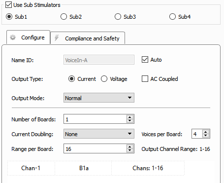 |
| IZV Stimulator Configure Tab Options |
The input signal format is a multi-channel signal where the odd channels contain the actual stim waveforms and the even channels contain the target stim channel. For an input that has 4 unique stim signals, it will be an 8-channel signal where channels 1, 3, 5, 7 are the stim signals and channels 2, 4, 6, 8 are the corresponding target stim channels. Information about the state of the channels between stimulation pulses (Channel Hold, Channel Release, Discharge, or Ground) is also encoded in the target stim channel signals. It is generally expected that this input signal comes from an Electrical Stim Driver gizmo so that it has the proper format. If you are trying to send arbitrary waveforms to the IZV, please contact TDT support for more information.
Sub Stimulator Options
The sub stimulator options in the Configure tab are described below. For more information on how to apply these options to your application, see Stimulation Types.
The data table at the bottom of the Configure tab shows the mapping between the gizmo input voices and the physical hardware voices. The first column is the voice of the "VoiceIn" for this sub stimulator. The middle column is the board number within the sub stimulator that it uses and the hardware voice on that board it uses (a, b, c, d). The last column is the range of channel numbers that the VoiceIn stim channels should address.
For example, an input from an Electrical Stim Driver gizmo with two voices on it targeting banks 1 and 2 on a sub stimulator would read as:
Chan-1 | B1a, B2a | Chans: 1-32
Chan-2 | B1b, B2b | Chans: 1-32
Safety
When Safety Mode is enabled in Synapse, the Subject Interface IZV must be armed by the user before any current can flow (see Runtime Interface below). The hardware ensures that maximum output current is not exceeded. The Subject Interface is battery powered and thus isolated from any mains power, when not charging. The safety configuration options for the IZV (Compliance and Safety) are below.
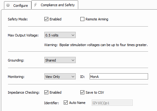 |
| IZV Stimulator Compliance and Safety Tab Options |
Runtime Interface
Safety Mode
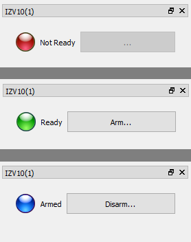 |
| States of the IZV Runtime Interface |
If Safety Mode is enabled on the Safety and Compliance Tab, then an LED will show the state of the compliance monitor. If Remote Arming is disabled, the Arm/Disarm button is shown and the device can be armed when ready.
Important
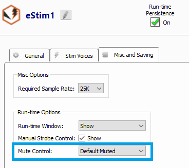
The system can only Arm if the fiber is connected and a zero current command is sent to the IZV, so make sure the gizmo controlling stimulation is muted. In Safety Mode, you can ensure the stimulation is muted when you start the recording by setting Mute Control to Default Muted in the Electrical Stim Driver gizmo 'Misc and Saving' tab.
Impedance Check
If Impedance Checking is enabled, the IZV provides an interface for impedance checking on all channels.
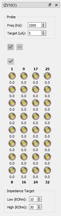 |
| IZV Impedance Check Runtime Interface |
The display represents the stimulation channels divided into sub stimulators. Set the test stimulus frequency and amplitude, and define the high and low impedance threshold targets for visualization.
Running the Check

Run an impedance check on the currently selected sub stimulator. The test signal (sine wave of frequency defined by Freq (Hz) parameter and amplitude defined by Target (uA) parameter) is presented iteratively on each channel in the currently selected sub stimulator for ~500 ms and the impedance is measured using the IZV built in compliance monitor.

Check All. Run an impedance check for all IZV channels using the test signal as described above.

Stop Checking. Stops the impedance checking prematurely.
Double-click on any individual LED to run the impedance check on that channel only.
Results of impedance check are indicated by color: below low impedance target (green), above high impedance target (red), between low and high impedance targets (yellow). The actual impedance values (in KOhm) are displayed beneath each indicator.
Impedance results are optionally saved in a CSV text file located in the data block folder.
Testing
Each IZV bank comes with an RB10 resistor block to verify the IZV output signal. The RB10 has a 10 kOhm resistor on each channel to ground.
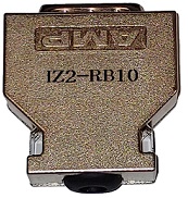 |
| RB10 Resistor Block |
Plug this directly into the Subject Interface IZV stim boards instead of a headstage and run an impedance check. The LEDs on the impedance check interface should indicate ~10 (kOhm) for each channel.
Each SW switching headstage comes with a ZCA32-RB10 or ZCA64-RB10 resistor block. If using a switching headstage, clip the switching headstage onto this resistor block and run the impedance check. The LEDs on the impedance check interface should indicate ~10 (kOhm) for each channel.
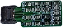 |
| Zif-Clip® Resistor Block |