Understanding Hardware Limitations
Please take a moment to review the Subject Interface Technical Specifications.
Important specifications particular to this guide:
Compliance vs Load Impedance
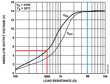
The Subject Interface IZV voltage compliance follows a curve that is load-dependent (figure to right). For impedance loads >3 kΩ the output compliance per card is ±15 V. At lower impedances, however, the output voltage compliance is reduced due to operation limits of the op amps in the IZV.
The user should note that the current compliance limit of ±5 mA for
loads <3 kΩ is strictly a consequence of Ohm's law (V = IR). Impedance
loads >3 kΩ would produce a voltage output larger than ±15 V at a 5
mA current. Since the output request in this case is current and not
voltage (current mode vs voltage mode), the voltage compliance curve
shown does not apply, as you will see later.
Output Impedance
Below are two diagrams that demonstrate what is occurring at a hardware
level when a stimulus is output in either Voltage Mode or Current Mode
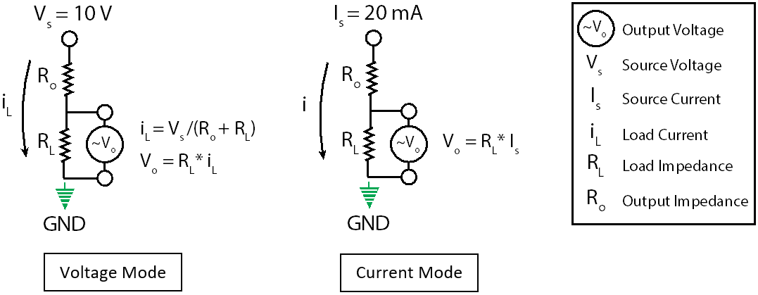
As stated earlier, the absolute output
voltage is limited by the impedance of the load resistor RL. Thus, the
measured output voltage Vo when in Voltage Mode may not meet the
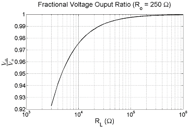
requested voltage Vs. The issue is further compounded because the
measured voltage Vo is affected by the output impedance Ro of the
IZV. The voltage drop Vo across RL follows the scheme of a voltage
divider, since some voltage is lost across Ro. Thus, your measured
voltage will always be less than your requested voltage Vs for all
impedance loads <3 kΩ or >3 kΩ, even if your requested voltage is
below the compliance limit (see Fractional Voltage graph for expected
loss and the example Voltage Mode oscilloscope output below).
In Current Mode, the requested current Is flows across both resistors
equally. Thus, the measured Vo is not affected by Ro (see example
Current Mode oscilloscope output below).
Using <3 kΩ Resistance Loads
Below are oscilloscope images that show the measured
voltage output across a 500 Ω resistor load (RL). The test was
performed in Voltage Mode and Current Mode to compare the compliance
limits for a targeted 10 V output. The voltage division for each graph
is 5 V.
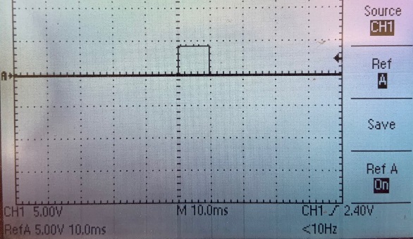 |
| Voltage Mode: RL = 500 Ω load, Vs = 10 V requested |
The measured voltage is slightly less than the compliance maximum of ~5 V for the 500 Ω load resistance due to Ro.
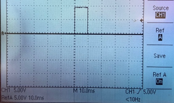 |
| Current Mode: Ro = 500 Ω load, Is = 20 mA requested |
Current Doubling: By Four
was active to achieve{5 mA * 4 Voices} current compliance maximum
V = {I * R}; 10 V = {20 mA * 500 Ω} to mimic the 10 V request test from Voltage Mode
The measured voltage is 10 V because we used Current Mode.