Template Experiments
Included with this guide are template experiments that help you set up and understand various IZV stimulation paradigms.
Choose an appropriate template based on your electrode impedance and desired current or voltage output. Use the tables below to guide you.
The templates are described in detail, and include a link to the Synapse experiment (*.synexpz) that is used. Please be sure to have your IZV10 and other appropriate hardware detected in your rig (Menu → Edit Rig → Detect) so there are no issues when importing templates.
These templates all assume at least 4 stim banks are available.
Picking a Template Based on Impedance and Desired Output
Note
The settings of each recommended templates may need to be modified depending on the desired electrode configuration (monopolar (single-ended) or bipolar). If the recommended template needs the output mode (current-mode vs voltage-mode) switched, there will be an asterisk*.
For options marked as 'Not Recommended', there may be workaround solutions. Please consult with TDT tech support for possible options.
Current-controlled (Monopolar)
Choose the tab for your electrode impedance below to see the recommended templates.
>3 kΩ
<3 kΩ
Current-controlled (Bipolar)
>3 kΩ (20 kΩ example)
<3 kΩ (500 Ω example)
Recall that a bipolar configuration in current mode allows up to
increase the effective voltage compliance because each phase is measured
with respect to a GND in the center of the anode and cathode. However,
it will not double the measured voltage across the load impedance like
in Voltage Mode. As you can see, the 500 Ω examples result in the same
output ranges as monopolar for current below 20 mA because V = I*R.
Voltage-controlled (Monopolar or Bipolar)
>3 kΩ (20 kΩ example)
<3 kΩ (500 Ω example)
* Change IZV10 'Output Type' to Voltage Mode
Voltage or Current Mode
Single Channel Across Four Boards (5 mA or ±15 V)
Single Channel Across Four Boards (5 mA or ±15 V)
This template is covered in the Quick Start Example
Single Bipolar Output (5 mA or ±30 V)
Single Bipolar Output (5 mA or ±30 V)
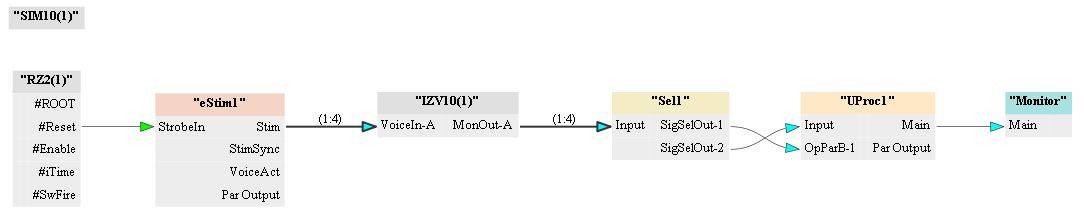
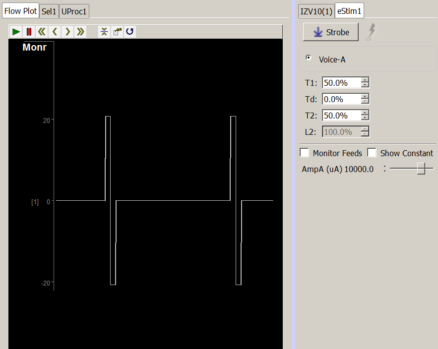
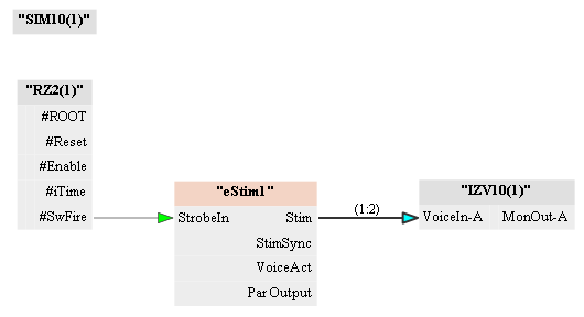
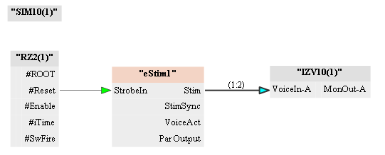
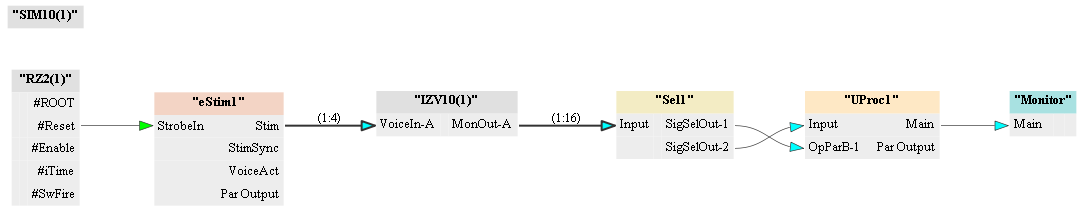
When performing bipolar stimulation, the IZV10 monitor output ('MonA') will likely not provide a meaningful readout of the stimulation across your load. The user must subtract the two bipolar channels from one another to see the voltage across their load. This is done using the following gizmos: Selector, Unary Processor, Stream Data Storage.
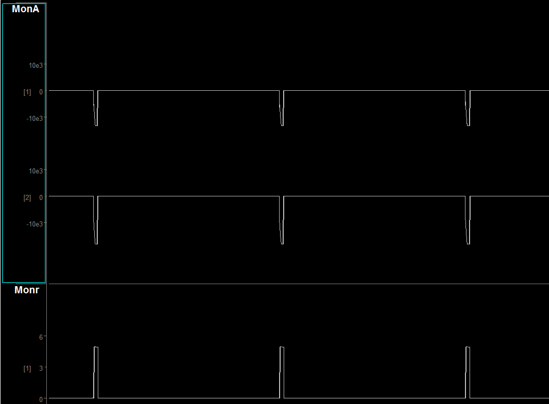
In this example shows the output of a 250 µA stimulation across a 20 kΩ load. The expected voltage is 5 V. 'Monr' is the output from the bipolar subtraction.
List of Channels and Parameters over a Specified Time Sequence
List of Channels and Parameters over a Specified Time Sequence
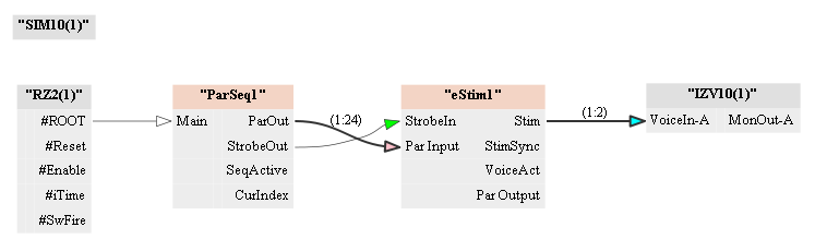
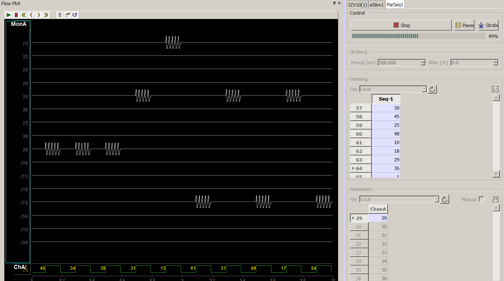
The Parameter Sequencer is a powerful gizmo that enables the user to sequentially change stimulation parameters and target channels in a well-defined timing and pattern. In this example, we are targeting random channels from all 4 banks (output range 1 - 64).
Note
You must either arm the IZV10 first or turn off safety mode before
beginning your stimulation sequence. Thus, if you have both Start Seq at Run-Time
and Safety Mode enabled on the Parameter Sequencer and IZV10, respectively, you
will not be able to stim.
Current Mode
Stimulating Up to 10 mA per Voice
Stimulating Up to 10 mA per Voice
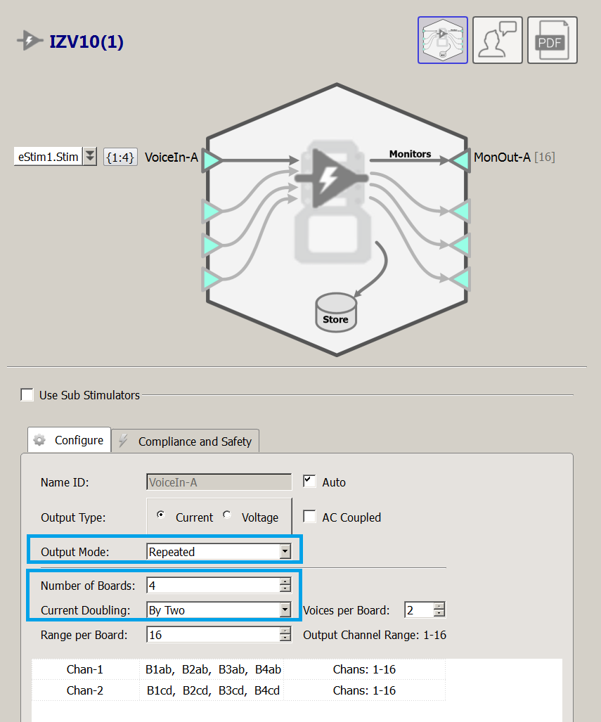
Setting the IZV10 to Current Doubling: By Two allows
the user to stimulate up to 10 mA per voice. This setting decreases the
max Voices per Board from 4 to 2. This is because, in order to achieve
current doubling, two voices are directed to the same output channel.
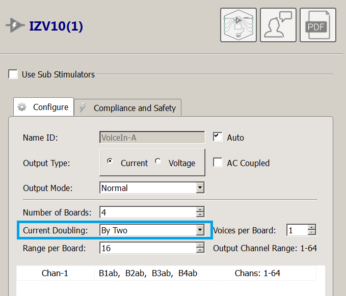
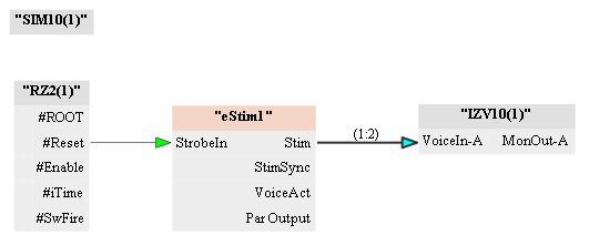
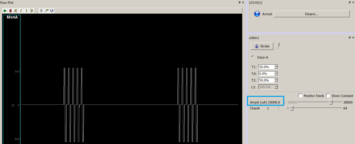
In this example, we are sending 10 mA across a 500 Ω load to achieve a ± 5 V biphasic voltage output across channel 1 (channel 1, board 1).
Stimulating Up to 20 mA per Voice
Stimulating Up to 20 mA per Voice
Setting the IZV10 to Current Doubling: By Four allows the user to stimulate
up to 20 mA per voice. This setting
decreases the max Voices per Board from 4 to1. This is because, in order
to achieve current doubling, four Voices are directed to the same output
channel. One can only perform single-ended stimulation with the Current
Doubling: By Four option since Bipolar and Local Ground require two
Voices per stim signal.
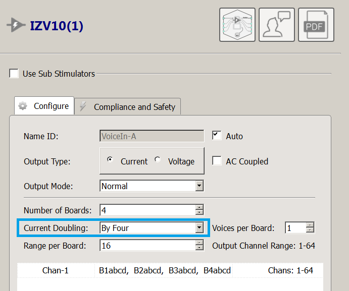
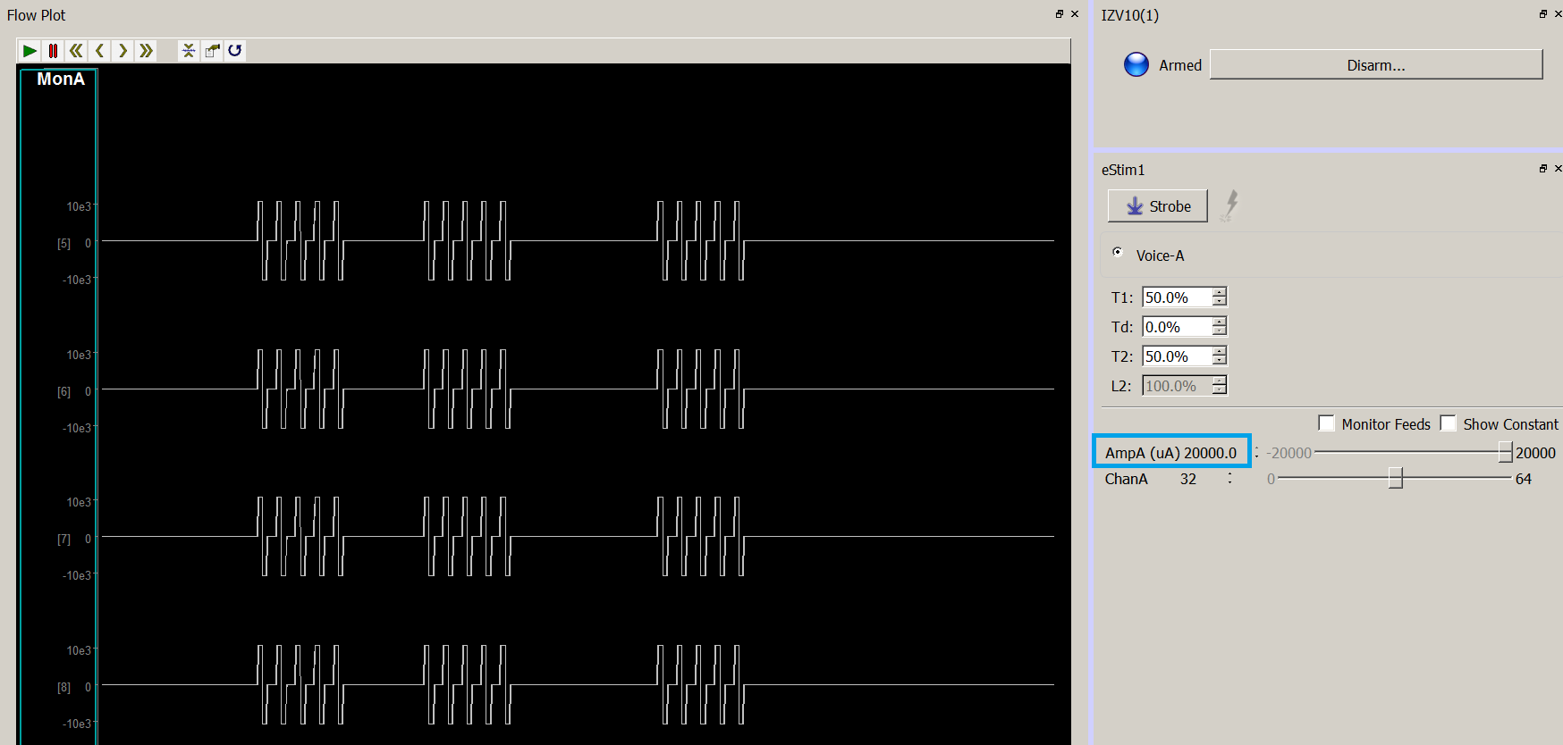
In this example, we are sending 20 mA across a 500 Ω load to achieve a ±10 V biphasic voltage output across channel 32 (channel 16, board 2).
Note
The output channels on the IZV10 'MonA' store (below) show
four stimuli trains on channels 5 - 8. This is because in Current
Doubling: By Four there are four Voices being played, but they target
the same output channel (recall that current sources in parallel add).
The range is 5 - 8 because the IZV10 monitor looks at 4 Voice monitor
streams per board.
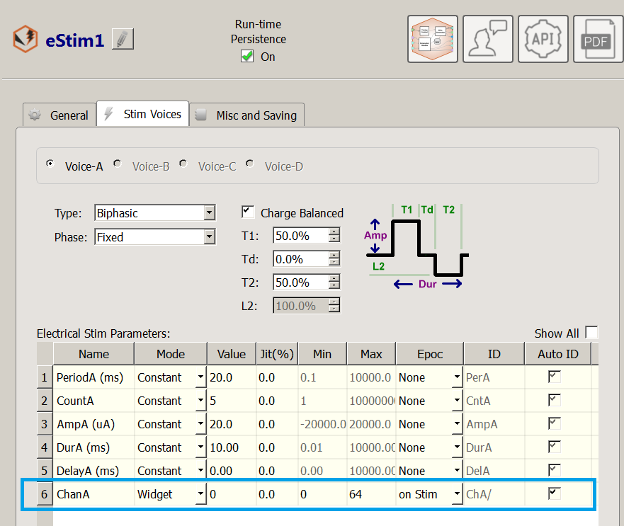
Recall from Quick Start: Understanding Stim Info that the target channel information is contained in the eS1r stream, or if you enable Epoc Storage for the Chan parameter in the eStimDriver parameter table (see eStim1 image below).
Serial Outputs
Stimulating Up to ±60 V in a Bipolar Configuration
Stimulating Up to ±60 V in a Bipolar Configuration
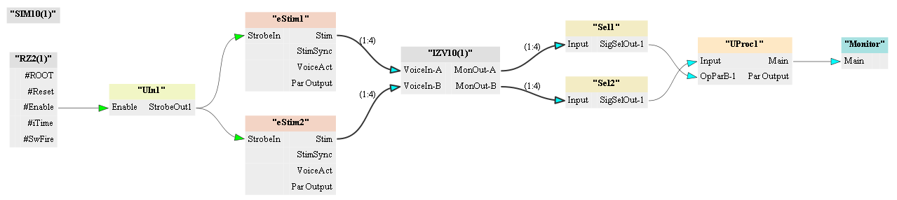
Serializing an output is useful for increasing the compliance voltage across a load. The user can manually configure a serialized output (as opposed to using Serial Mode) using 2 or more boards. Recall from Serial Outputs that this is a bipolar configuration, and that specific channels are shorted together to achieve the hardware configuration.
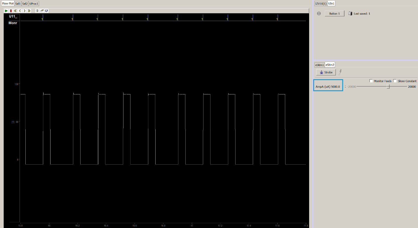
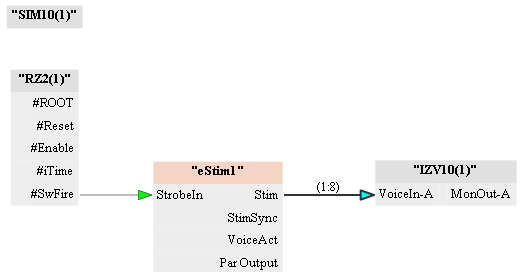
The connection diagram is showing the serial output setup. A User Input gizmo (UIn1) is used to synchronize the output timing of two eStim waveforms. The eStim1 and eStim2 waveforms are inverses of one another and are sent to either sub stimulator 1 or sub stimulator 2 of the IZV10. The Selector Unary Processor Stream Storage Gizmo is to monitor the true bipolar output. The equation in the Unary Processor reduces to the serial output equation specified earlier once the subtraction of inverse signals is accounted for: {2 * requested voltage * Nbanks}.
Here is the output from a 15 V request using channels 1 and 16 in
Voltage Mode. The output is +60 V across an open load.
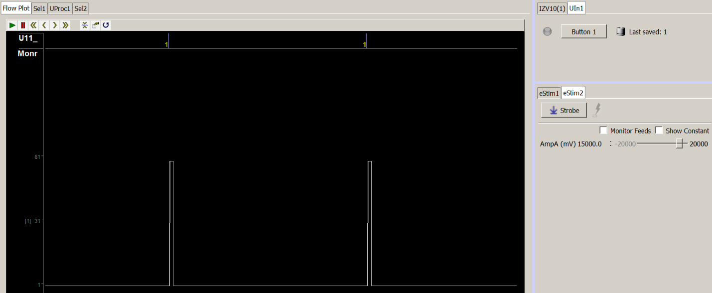
Note
The load is open to demonstrate max compliance.
Recall
that, in Voltage Mode, for a non-infinite load impedance there is some
voltage loss vs the max compliance due to the output impedance of the
stim.
Stimulating Up to ±120 V in a Bipolar Configuration
Stimulating Up to ±120 V in a Bipolar Configuration
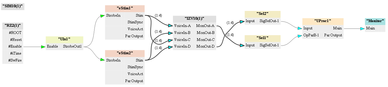
The connection diagram is showing the serial output setup for four boards. The same paradigm that was used in a two-board serial configuration is applied here.
A User Input gizmo (UIn1) synchronizes the output timing of two eStim waveforms.
The eStim1 and eStim2 waveforms are inverses of one another and are sent to either sub stimulator 1, 3 or sub stimulator 2, 4 of the IZV10 to achieve the waveform setup outlined in the Serial Outputs diagram for 4 board serialization.
The Selector Unary Processor Stream Storage Gizmo is to monitor the true bipolar output. The equation in the Unary Processor reduces to the serial output equation specified earlier once the subtraction of inverse signals is accounted for: {2 * requested voltage * Nbanks}.
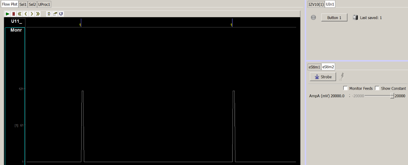
Here is the output from a 20 V request
using channels 1 and 16 in Voltage Mode. The output is +120 V across an
open load. This is because the compliance is still +15 V per Voice, so
the 'requested voltage' here is 15 V and not 20 V.
Stimulating Beyond 5 mA with Impedance Loads Greater than 3 kΩ
Stimulating Beyond 5 mA with Impedance Loads Greater than 3 kΩ
The setup is nearly identical to the Voltage Mode setup. The main
difference is that the user can easily setup Current Doubling: By Two in
order to increase the current compliance from 5 mA to 10 mA per Voice
across the load. Recall from Current Mode
that the current across the load is the requested current and not
2*requested current, so the voltage compliance increased but the
voltage output is still just V = I*R.
In this output example, we are stimulating 5 mA across a 20 kΩ resistor to achieve an output voltage of 100 V. In a normal configuration, the max current we could send across a 20 kΩ load is 750 µA {V = I*R; 15 V = 750 µA * 20 kΩ}. However, because we serialized the boards together, the voltage compliance is increased to {2 * Voice voltage compliance * Nbanks}, so we can send the full Voice current limit of 5 mA across the load.
Repeated Mode
Duplicating Stim Signals On Many Banks
Duplicating Stim Signals On Many Banks
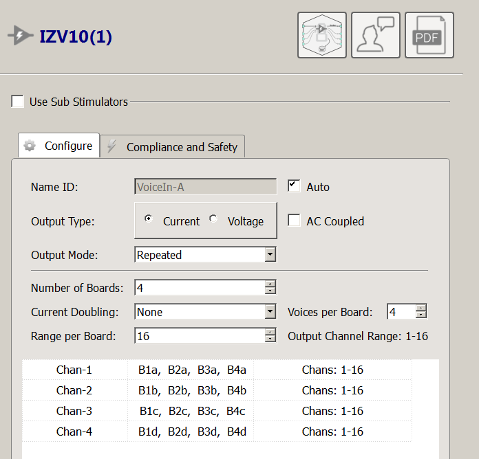
Repeated Mode is an easy way to send the same stimulus to identical
target channels across multiple boards. In this mode, the 'Output
Channel Range' is 1 - 16, even though more than one board is active in
'Number of Boards'. In Repeated Mode channels in higher board numbers
are addressed as if they were on board 1. This is because the same Voice
is repeated on every board in the sub stimulator.
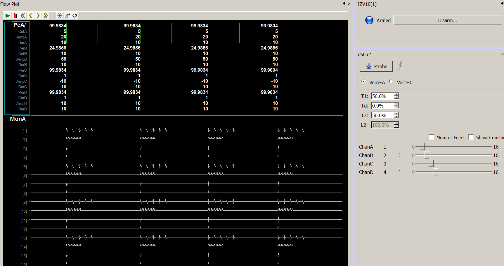
In this example, we are repeating four different Voices on 4 boards. ChanA addresses the first Voice on boards 1 - 4, ChanB the second Voice, and so forth. The notation 'B1a', 'B2a', 'B3b', etc. refers to BoardN, Voice A - D. Chan-1 controls Voice A on boards 1 - 4, Chan-2 controls Voice B on boards 1 - 4, etc.
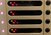
The LEDs on the SI-8 board indicate voltage activity during the
stimulation trains. All four boards repeated the same LED activity
because they had the same stimulation signals.
Parallel Outputs and Parallel Mode
Sending 16 Unique Signals to a 16 Channel Output
Sending 16 Unique Signals to a 16 Channel Output
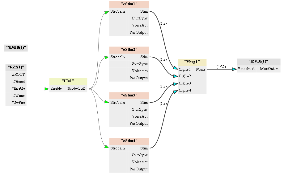
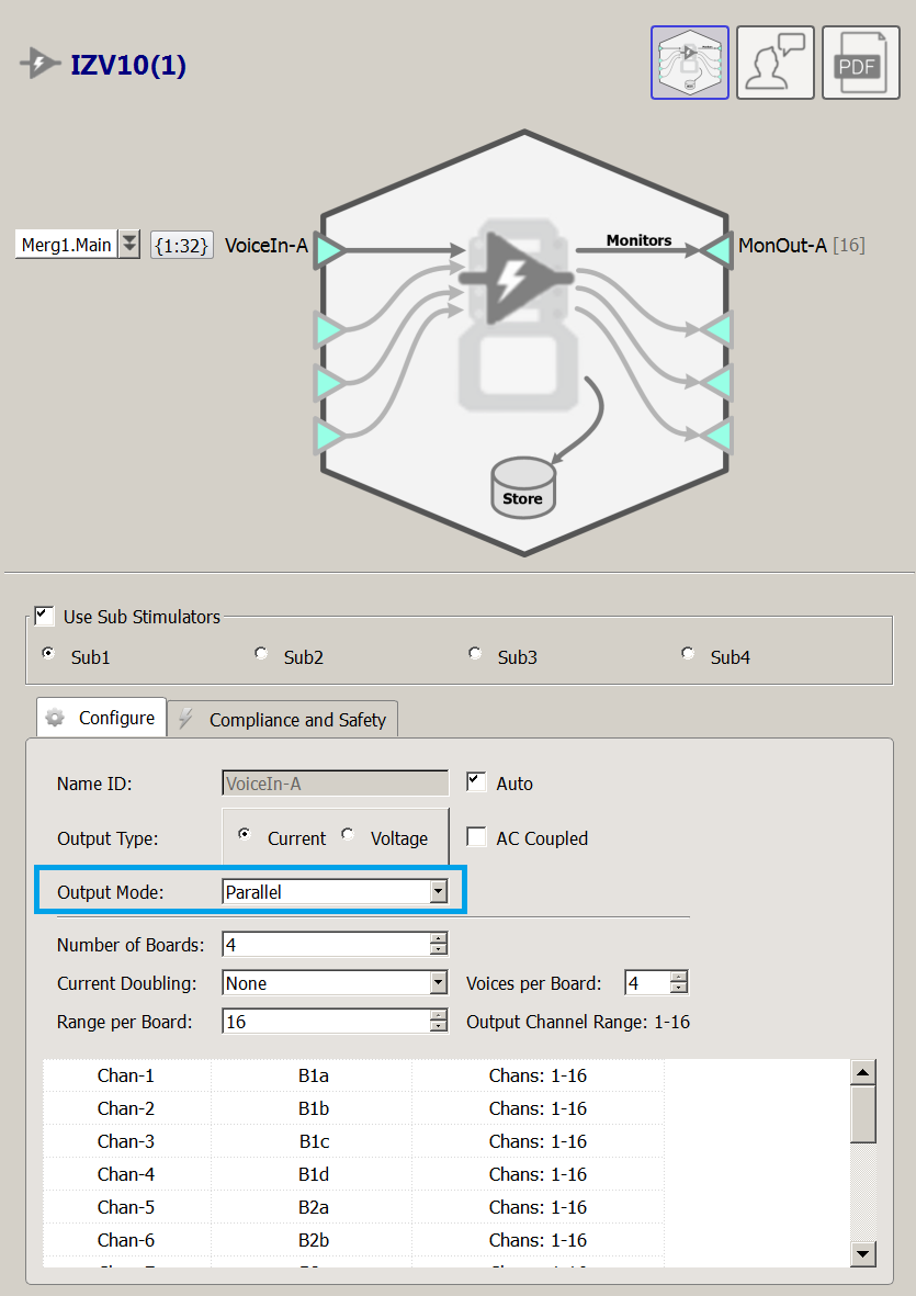
The connection is showing a Parallel Mode output of 16 unique Voices over four banks. Each eStim gizmo can output four Voices and four Channel Number signals. The eight signals from each eStim gizmo are then merged to create one multi-channel signal to inform the IZV10.
The 'Output Channel Range' is limited to 16 and each board range is 16 in Parallel Mode. This is because Parallel Mode assumes the outputs from each board are physically shorted together. Use the SI-MUX4 adapter for this (or the SI-MUX2 adapter for a 2 bank configuration). This makes a single output set. In this example, 16 unique voices can target 16 individual channels on an electrode array. Each channel in the parallel configuration is addressed within a range of 1 - 16 instead of 1 - 64 to make the configuration easier to understand. Channel '1' is the actual first channel for all boards in the sub stimulator, in this case, and so forth up to channel '16'. Please refer to the Parallel Outputs section for more details.
Stimulating Greater than 20 mA Across a Monopolar Electrode
Stimulating Greater than 20 mA Across a Monopolar Electrode
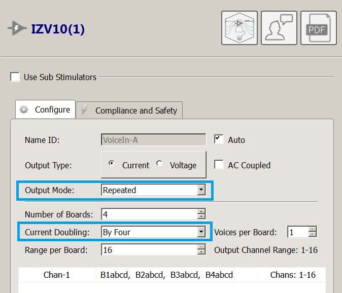
Some experiments may require very large current outputs (>20 mA) which cannot be achieve through Normal output mode configurations. In this case, the user can short outputs of each board together to make a parallel current output. The easiest way to do this is to make use of Repeated Mode and Current Doubling. In this example, we are sending 7.5 mA from a Bipolar Voice repeated four times across a 500 Ω load. This provides a 30 mA current, since current sources in parallel add together.
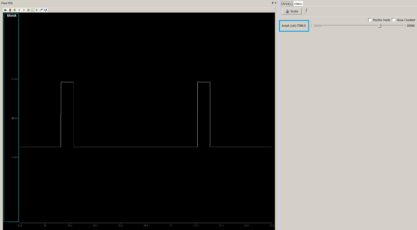
The result is a 15 V output across our load. {7.5 mA * 4 Voices = 30 mA; 15 V = 500 Ohms * 30 mA}
Stimulating Greater than 10 mA Across a Bipolar Electrode Pair
Stimulating Greater than 10 mA Across a Bipolar Electrode Pair
Some experiments may require a bipolar electrode configuration with currents beyond the Normal output mode limits for bipolar Voices (10 mA). In this case, the user can short outputs of each board together to make a parallel current output. The easiest way to do this is to make use of Repeated Mode and Current Doubling. In this example, we are sending 10 mA from a Bipolar Voice repeated four times across a 500 Ω load. The result is a ±20 V output, which is a 40 mA current. Recall that a bipolar configuration allows up to increase the effective voltage compliance because each phase is only 10 V with respect to GND.