Troubleshooting
RPvdsEx Known Anomalies
General
Moving Between RPvdsEx Circuits
In version 44 and higher, moving between RPvdsEx circuits when one circuit is running can produce the following error: "zBUSError Call RpxgetCmpPar zError Specified memory area not valid". This occurs if a second circuit (to the same device) is run at the same time. This error also occurs when two RA16 base stations are connected together and a base station, other than the one connected to the amplifier, has a compiled circuit file loaded to it. The error message cannot be removed without closing RPvdsEx. End RPvdsEx using Ctrl-Alt-Del, Task Manager -> Applications, select RPvdsEx and click End Task.
Network Printers
If printers are added to your system, RPvdsEx documents generated before the printer was installed may take an inordinately long time to load (>10 minutes). Disconnecting the computer from the Network or uninstalling the printer driver will usually solve the problem. The file can also be loaded, reduced, copied, and pasted into a new document.
RA16 Cycle Usage Error
In version 41 and higher, when two RA16s are connected via a fiber optic cable, under certain conditions, the RA16 connected to an amplifier may display incorrect cycle usage. RA16s up the chain from the amplifier must all be set to the same sample rate. If using two RA16s, make sure both have circuits running on them and that the first circuit run is for the RA16 connected to the amplifier. If only using one RA16, disconnect the fiber optics to the other base stations.
Technical Support File Format
If you are using version 45 or below you may be unable to open .rpd files provided by Tech Support. If you cannot upgrade to the latest version of RPvdsEx, Tech Support can send screen captures of the circuit.
RX8 Device Setup
The RX8 allows sample rates up to 100 KHz, however RPvdsEx may allow the user to enter arbitrary sampling rates above 100 kHz in the RX8 Device Setup. When entering arbitrary sampling rates in the RPvdsEx Device Setup, enter only sampling rates that are supported by the device, i.e. up to 100 kHz for the RX8.
Parameters
CmpNo Parameters
Because component numbers are assigned when compiling the circuit; the user must check the "CmpNo" parameters on components, such as ReadBuf and HrtfCoef, to make sure they are set to the right value every time the circuit is recompiled. If the circuit is run with the "CmpNo" parameter set to the wrong value, the circuit will not work correctly and a hardware reset may be required.
Phase Parameter
The phase parameter of the waveform generator components (Tone, RampTooth, and SawTooth) must be greater than -180 and less than +180. Any value (including exactly -180 or +180) outside of these bounds will be set to a phase of zero. If a phase of exactly 180 is needed, use 179.999 instead. To alternate between opposite phases, use a ScaleAdd component to flip the sign of the waveform.
Components
State Machine
In v66, the StateMachine component may reset unexpectedly when the circuit is compiled. Contact TDT for an updated version of RPvdsEx.
When Enable is high (=1) and Reset is low (=0) the state of the machine does not correctly change states even when the correct JmpA and JmpB inputs are set. The Enable input must be triggered with a rising edge simultaneously with the JmpA and JmpB input values in order to change states.
Arccos, Arcsin, and Arctan
The Trigonometry components: Arccos, Arcsin, and Arctan have slight rounding errors and should not be used in applications requiring very precise values, until they are fixed in a new version. For example: Arccos(-1) should be pi (3.14159), but the component's output is 3.09164
Bin Rate
BinRate records one spike during each of the first two samples of running the circuit. The easiest workaround is to ignore the first two spikes counted. See BinRate for an alternate solution.
Cos2Gate and LinGate
If a Gating component (Cos2Gate or LinGate) is controlled by a Schmitt component, invalid output values may occur. If a ParWatch is connected to the output of the gating component, the invalid output value will display as "-1#QNAN". If the invalid output occurs consistently, the circuit file should be re-created.
Destination File
The DestinFile component always writes out a 32-bit raw floating-point file, no matter what file type is specified. Other formats, such as wav and .txt files, are not supported at this time. A 16-Bit integer format ('.I16') can also be used if the 'Comp to 16' component is used to convert the data to 16 Bit integer format before transferring it to the destination file.
Feature Search
The Peak, Valley, and Tip conditions in the FeatSrch component are not always correct for frequencies less than 2 Hz.
Find Frequency
The FindFreq component takes longer to stabilize (>10 sec) when the input frequency is less than 0.5 Hz. An incorrect value is returned when the input frequency approaches zero (\<0.005 Hz).
FIR and FIR2
Loading a large number of coefficients to an FIR or FIR2 filter can take several seconds when using a USB PC-to-zBus interface. Because coefficient values are loaded to data memory, which does not support block reads and writes, values must be loaded from the PC to data memory one value at a time. When using a USB interface this can take between 1 (USB 2.0) and 5 (USB 1.0) milliseconds for each write. Coefficients on the order of 1000 points can take over a second to load.
MCFIR and MCFIR2
A memory allocation error in the MCFIR and MCFIR2 components causes erroneous results if the number of channels is set to be greater than the number of taps.
Modulus
The Modulus component gives incorrect output for some inputs. The problem occurs when modding a multiple of the Mod parameter, i.e., when doing Kx mod x for some nonzero integer K. This component should not be used until it is fixed in a new version.
SimpCount
The SimpCount component runs on every sample, even when it is put into a time slice.
Tan
The Trigonometry component Tan gives incorrect values and should not be used until it is fixed in a new version.
WordIn/WordOut
Beginning with TDT Drivers version 57 and RPvdsEx version 5.4, the WordOut and WordIn components are implemented differently. A Bitmask value of -1 should no longer be used.
Common RPvdsEx Error Messages and Warnings
Error Loading RP Circuit
This often indicates that RPvdsEx is not recognizing your processor. The device should appear in the hardware diagram in the zBUSmon utility if it is recognized. If it does not appear, check your connections and cables. If the device is recognized:
- Ensure that your circuit does not contain more than the maximum number of components for the processor selected in the hardware setup.
- Exit the RPvdsEx program (after saving any circuits) and restart RPvdsEx (make sure that no other RPvdsEx programs are loaded).
- Exit out of RPvdsEx, reset the hardware (hardware reset button on the zBUSmon program), restart RPvdsEx, and rerun the circuit.
- Shut off the zBUS device chassis (always remove battery operated units before powering down) and turn the RP system back on. Restart RPvdsEx.
If you still receive this Error message contact TDT at support@tdt.com.
Data type mismatch: ....
Input and output ports are color-coded by data type for easy identification. When necessary, use Type Conversion components to convert the signal to the appropriate type.
Link cannot originate from 'Input' port or Link cannot terminate at 'output' port
These messages may occur for several reasons:
- The connection direction goes from a parameter tag to a port. The parameter tag is a "pointer" to the value in the port. No matter what direction the parameter tag points, the connection is always from the parameter tag to the port value.
- The output port connects to a signal input and not a parameter input. This occurs when you are attempting to make a parameter value a signal. For example AND, OR, and SUM ports all require that the input is a signal.
Apparent nChannels mismatch between connected components
Mismatched channel number parameters cause warnings (rather than errors) when the circuit is compiled and do not prevent the circuit from running. If the multi-channel input includes more channels than specified in nChan, the excess channels will be ignored. If the multi-channel output has fewer channels than specified in nChan, then the excess channels will be undefined. When using macros, setting the channel number parameter in the macro setup ensures that all component channel numbers in the underlying circuit will match. RPvdsEx also includes a convenient global replace for channel numbers that can help ensure matching channel numbers are used.
Components intersecting Iterator
The indicated process is not fully contained in the Iterator box. It may be necessary to use HopIn/Out pairs to fully contain the process.
MCHop source is not found for component
A multi-channel HopFrom component is missing an input. Ensure that Hop component labels match, including case, and when indexed hops are used, ensure that there is a hop for each channel.
zBus Error: Call RPxAddCmp / zError: Memory Allocation Failure
If you have a Stingray processor this often indicates that the Stingray is undocked, or has a low battery. Check the status lights to make sure that the Stingray is docked to the system. All lights should be on. If any light is off or flashing redock the Stingray. If this fails, do a hardware reset. Go into the zBUSmon program on your desktop and press the hardware reset button.
Before Debugging a Circuit
The first step in debugging a problem with a circuit is to decide if it is a hardware or software problem. The steps provided in this section will help you make that determination. Before you follow these steps make sure that the drivers, RPvdsEx software, and microcode on the RP/RM/RZ module are the same. (See The zBUSmon Window in the System 3 Manual .)
Hardware problems are, in general, not affected by the circuit you run. They can include:
- Bad cables (no sound or noisy signal). The first thing to check is the patch cables. If they are faulty it will cause many problems with your system. (See below for more information on checking for cable problems.)
- Bad DAC's (no sound, distorted signal). Test the output with a simple circuit such as a tone connected to a DAC out.
- Bad ADC's (noisy signal input, distorted signal). Test the input by playing a tone out and then a tone in to a serial buffer.
- Bad USB device module (RP modules disappear from zBUSmon). This can be caused by static discharge. If the RP module disappears while running a simple circuit (such as tone out) it may mean that the USB module is bad.
If you experience hardware problems, other than cable problems, contact TDT technical support at 386-462-9622. If you suspect that your problem is software or cable related, check for cable problems before debugging.
Checking for Cable Problems
To make sure that all the patch (BNC) cables are in good condition, run simple circuits. The following circuits should work under all conditions:
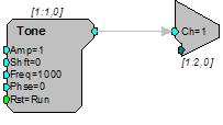
Tone circuit with a single tone generator and a single channel out. Send the output from Channel 1 of your module to a headphone buffer, speaker, or Oscilloscope. If the sound plays out it indicates that the system is working.
The following acquisition circuit uses the Tone circuit above to generate a pulse, store it in a buffer and send it back to the PC to be graphed.
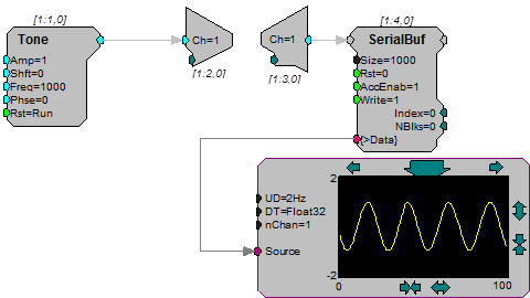
If this circuit above does not work for you there are three possibilities.
The cables are bad and you should try a new set of cables.
The cables are connected incorrectly. Make sure that IN 1 and OUT 1 are set up correctly.
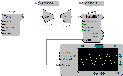
The circuit is not running. Connect a parameter watch to the Tone out to see if it is running and also to the Ch=1 to see if it is acquiring signals.
Common RPvdsEx Problems
This section focuses on common circuit design problems. If the Compile, Load, Run arrow is grayed out, check your hardware for problems. If you have encountered an error message, see Common RPvdsEx Error Messages and Warnings.
Component Incompatibility
When a circuit that was compiled after upgrading both the TDT Drivers and the microcode does not run or crashes a device, the problem typically relates to the components in the circuit. Newer versions of RPvdsEx include components that are not supported on all devices. You might have used a component in the circuit that is not supported by the device. For example, multi-processor and multi-channel components will only run on the new multi-DSP devices, such as the RX5, and RZ2.
Quick Solutions to Common Problems
Serial Buffer does not record or play out.
- Make sure the AccEnab line is set high.
- Make sure that the buffer size is large enough for the signal.
- Make sure that the write Enab is set to 1 to store data to a buffer or 0 to read.
Pulse Generator does not send out a pulse.
- Check to see if the enable line has been triggered or is set to 1.
Debugging a Circuit
If you have trouble getting a circuit to run there are several things to try:
- Check that you are not exceeding maximum cycle usage. To do this place a cycle usage component and connect it to a parameter watch.
If you exceed maximum cycle usage you have several options:
- Run at a slower sampling rate, which will give you more cycles (i.e. operations) per sample
- Run functions that do not have to be calculated on every cycle in a specified time slice.
- Break up the processing chain so that it runs on more than one RP device (single processors) or DSP (multi-processors).
- Use the Parameter Watch to inspect values at different points in the circuit.
- Load a Memory Buffer with data and then use the graph to view its contents.
It is possible to crash an RP device (For example, by writing over memory). Usually you will get an error message indicating difficulty communicating with the RP device. The only way to recover from this is to exit RPvdsEx, and power down the zBUS containing the RP device. Wait a few seconds before powering back up.
Note
When the RP2 is powered up, the lights on the Dout LEDs on the RP2 normally strobe repeatedly from 0 to 3. The Din lights normally stay lit.