Buffer Operations
Buffer components are used to create and access data buffers. Data buffers can be used to store signals, prepare for averaging, or create complex mappings. Most buffer operations (AvgBuf, SerialBuf, and RamBuf) are associated with some amount of physical memory that can be accessed by that component. For example, adding a SerialBuf component to a chain will result in the required amount of SDRAM memory being allocated and associated with the component. Other components (such as, ReadBuf and WriteBuf) utilize another component's memory buffer. Because the RP2-5 does not have any SDRAM, it cannot make use of the buffer operations.
Changing the Buffer Size Dynamically
For some Buffer components size is a dynamic parameter, allowing users to allocate a variable size to the buffer from an application outside of RPvdsEx. However, when the RPvdsEx circuit is first run, a memory buffer is allocated based on the size. The size cannot be increased beyond the allocated memory. So, size can be changed dynamically, but it can only be decreased.
This group includes the following components:
- AvgBuf
- AvgBuf2
- BlockAcc
- BlockAvg
- RamBuf
- ReadBuf
- SerialBuf
- SerSource
- SerStore
- SnipStore
- TagStore
- WriteBuf
This group also includes the following components, if RPvdsEx Device Setup is configured for a high performance device, such as the RXn or RZn:
Comparing Buffer Components
This table provides a quick reference summary of the features of the buffer components.
* The enable lines of some of these components require a high signal for the duration of acquisition (For example: AccEnable in AvgBuf) and are classified as Enable lines. In other components, these lines are triggered to start and continue acquisition for a fixed number of samples (for example: StEnable in BlockAcc) and are classified as Triggers.
^ For some Buffer components size is a dynamic parameter, allowing users to allocate a variable size to the buffer from an application outside of RPvdsEx. However, when the RPvdsEx circuit is first run, a memory buffer is allocated based on the size. The size cannot be increased beyond the allocated memory.
So, size can be changed dynamically, but it can only be decreased.
AvgBuf
Description:
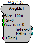
Implements a summer in memory (to get the average divide by the number of blocks at the end of acquisition). On each tick of the sample clock, where the AccEnable is high, a sample will be acquired and summed with the current value at the current index position in the buffer. The internal index generator is incremented with each acquisition and loops back to 0 when the total number of samples specified in the Size parameter have been acquired and summed.
Index reports the value of the internal index generator. NBlks reflects the number of times the AccEnab input is enabled and disabled and can be thought of as a block counter (assuming Size equals the block size fed into AvgBuf and AccEnable remains high for the entire block acquisition then goes from high to low between blocks). These outputs can be accessed from software or used within the circuit.
AvgBuf is often used with the BlockAcc component, which is enabled with a single enable pulse at the beginning of the block and then outputs an enable line that remains high for exactly the specified (BlkSze) number of samples.
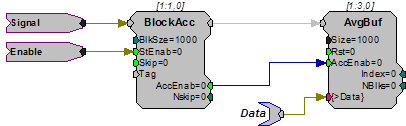
Interleaved averaging can be performed by writing blocks that are smaller than the buffer size allocated. For example, to calculate two interleaved averages of 500 points, use BlockAcc to write 500 point blocks to AvgBuf with size 1000.
Example:
Averaged Buffer
File: Examples\AvgBufex1.rcx
Default Device: RP2.1 Processor
Sampling Rate: 50 kHz
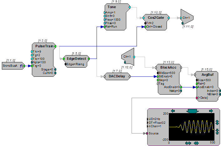
This example implements averaging using the AvgBuf component. A zBus trigger starts a pulse train with 100, 9 ms pulses with a gating time of 2 ms. These pulses trigger a Cos2Gate to generate 9 ms tones with a 2 ms rise/fall time. The pulse train is also used to write a block of 500 points (10 ms at ~50 kHz sample rate) from the ADC input to the AvgBuf component, which sums these points into its 500 point buffer. A DACDelay is used to synchronize the signal out to the data acquisition. A graphing function allows the user to see the results of the acquisition.
AvgBuf2
Description:
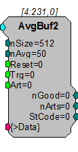
AvgBuf2 sums two alternating signals, acquired on a single input line. AvgBuf2 differs from AvgBuf in four ways. 1) It sums two signals separately. 2) It allows for variable buffer size. 3) It allows for artifact rejection. 4) It has an internal block access feature for acquiring each signal. In addition, AvgBuf2 has two additional buffers that hold the raw signal before the sums are complete.
When using AvgBuf2, the buffer size (nSize) is defined as the number of samples to be included for each signal. For example, if nSize = 512 then two buffers of 512 samples each are acquired. The nAvg parameter is used to define the number of blocks to be acquired and summed for each signal. A trigger starts the acquisition for each individual buffer.
Two triggers (one for the first buffer and one for the second) are required to acquire signals for both buffers. When the number of triggers presented to the Trg input reaches nAvg, the next trigger delivered moves the first sum to the first average buffer and finally, one last trigger is required to move the second sum to the second average buffer. The average buffer stores a sum of data blocks. In order to get their average, the user must divide each sum by the number of good acquisitions (nGood).
The nGood and nArts outputs provide access to current status for the number of good acquisitions and artifacts, respectively, for the current average. If artifact rejection is required, the Art parameter can be linked to a logical input. If Art goes high for any sample within the acquisition time of the current block, the block will be rejected. So, for example, if nSize = 100, and the processor is running at 25 kHz, then Art has to be within 100 * 1/24414 = 4.096 ms from the start of acquisition of a block.
StCode tells the user which one of the two signals it is currently acquiring. StCode 1 indicates acquisition to the first buffer and StCode 3 indicates acquisition to the second buffer. StCode 8 indicates the end of the data acquisition for a pair of average buffers.
Example:
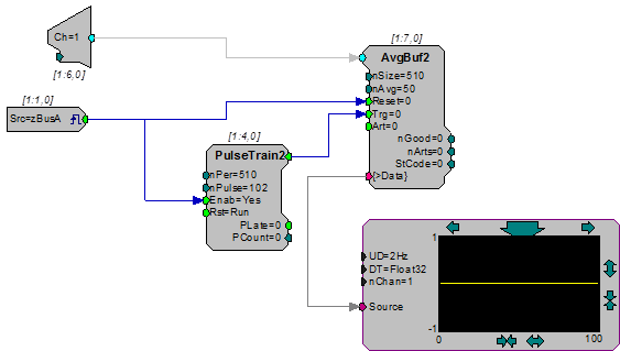
Averaged Buffer - The example below acquires and sums 50 blocks into each of the two buffers on AvgBuf2. The raw data is stored in a separate buffer before it is moved to the average buffer. Before the raw data is moved it can be deleted using the artifact rejection line. The values of the stored or average buffer (viewed in RPvdsEx using >Data) represent the previous summed signal values and not the values of the block currently being acquired.
Note that the pulse train is set for 102. For each buffer, the Trg must be pulsed once for each block that is to be summed. Two additional trigger pulses are required to move the data from each sum buffer to the average buffer. In this case there are two buffers with 50 blocks each, so [2(50) + 2] pulses are needed to complete the acquisition and store the summed data.
BlockAcc
Description:
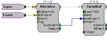
BlockAcc (block access) is designed for use with SerialBuf and AvgBuf to support block read/write functions. When the enable (StEnab) line is high, the AccEnab output will go high for BlkSize ticks of the sample clock.
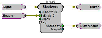
To support block marking, the BlockAcc has a Tag input. The value of the Tag input will be written as the first element of each buffer block. Also, to support artifact rejection in averaging, a Skip input is provided to allow buffer average skipping. If the skip line is made high, the next time StEnab is detected high it will be ignored and the Nskip output will be incremented by one.
Example:
Block Access
File: Examples\BlockAccEx.rcx
Default Device: RP2 Processor
Sampling Rate: 50 kHz
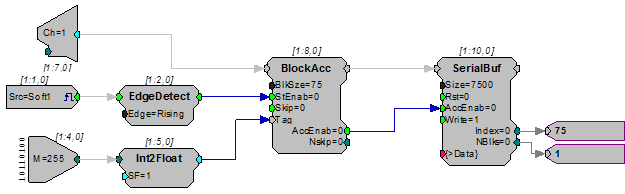
The example circuit shown below will save 75 samples from A/D input channel one each time the software trigger 1 goes high. The EdgeDetect component ensures that for one cycle of the sample clock, a high is sent to the BlockAcc StEnab input for each rising software trigger. The 75 samples will be saved to a SerialBuf with room for 100, 75-element blocks. Each block of data written will include a Tag value written as its first element. This circuit will write the eight-bit value at the digital input port as the tag value (the first value of each block). The eight-bit value is read using the WordIn component with bitmask 255. This integer value needs to be converted to float values to be consistent with the data stored.
BlockAvg
Description:
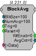
BlockAvg (block average) was primarily designed for use in OpenEx and TDT macros. Use the Block_Avg_Store macros for data averaging when possible.
BlockAvg acquires a selectable number of input blocks, summing them as they are acquired. Input blocks may be scaled before being fed to BlockAvg, to achieve an average when the specified number of blocks are summed. The accumulated sum is available on the output port when WrEnab is high. The input and output ports are equal except when WrEnab goes high, at that time, the sum is available.
Note
This component is for use with only high performance processor devices, such as RXn or RZn.
Example:
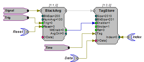
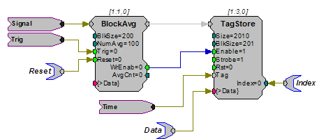
Block Average - In the example below, BlockAvg acquires samples of the input signal each time Trig goes high. Each sample is summed with the accumulated sum until 100 samples have been acquired (set by the NumAvg parameter). The accumulated sum is output and WrEnable goes high to clock the data into the TagStore component with the Time parameter tag. The current sample count is monitored on AvgCnt and is reset to zero by a logic high on Reset.
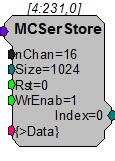
MCSerStore
Description:
MCSerStore stores data from a multi-channel signal. The data port (>Data) provides access to the buffer so that data can be downloaded to the PC.
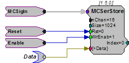
If WrEnable is high, values from each signal in the multi-channel input are read and stored in the next nChan buffer positions on each tick of the sample clock. The index is also incremented to the next nChan buffer positions. This means that data from all channels is stored in an interleaved fashion. The internal index generator is incremented until the total number of samples specified in the Size parameter has been written.
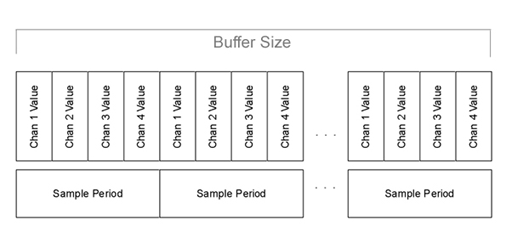
When the index reaches the end of the memory buffer, it automatically wraps back to zero and continues to increase from there. Any data currently in the buffers will be written over. Size must be set to the total number of points for all signals in the multi-channel input (Size = number of points in each signal * nChan). Size is a dynamic parameter, which allows users to specify the size of the buffer after the circuit has been loaded to the device.
There are currently no multi-channel versions of other buffer components, such as SnipStore or AvgBuf. Users who require these special features available with these components will have to convert the multi-channel signal to single channel.
Note
This component is for use with only high performance processor devices, such as RXn or RZn.
MCSerSource
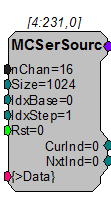
Description:
MCSerSource creates a multi-channel signal. Data can be written to the buffer via the data port (>Data). IdxBase and IdxStep control which index is being sent out of the buffer.
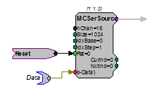
IdxBase defines the index into the buffer of the first output channel. The next nChan-1 values in the buffer are output on the remaining channels. The index is incremented by IdxStep*nChan on each sample. When the index reaches the end of the memory buffer, it automatically wraps back to IdxBase and continues from there. Set IdxStep = 0 and Rst=1 to hold the index constant and equal to IdxBase.
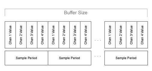
Size must be set to the total number of points for all signals in the multi-channel input (Size = number of points in each signal * nChan). Size is a dynamic parameter; the size of the buffer can be set after the circuit has been loaded to the device.
All channel data is stored in an interleaved fashion.
Note
This component is for use with only high performance processor devices, such as RXn or RZn.
RamBuf
Description:
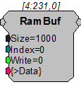
Implements a random access memory function. The RamBuf processing component is used to allocate and optionally access a buffer located in external SDRAM memory. Buffers can be any size (limited only by the amount of installed memory). When placed in a processing chain, RamBuf can be used to save data, play arbitrary waveforms, create complex mappings, or access specific data points in a buffer.
The index parameter controls the currently accessed buffer position. Index can have any value from 0 to Size-1. However, if the Buffer size is smaller than the index the index will overshoot the buffer size and the data accessed will be invalid.
The accessed buffer position will automatically be calculated as the modulus (Index/Size). The Write parameter is set to 0 for reading the index in memory. The Write parameter is set to 1 to write the current input value to the current index.
The output will always reflect the last value written to the current buffer location. So even if Write is made true and the current signal input is written to the memory, RamBuf will first read the old value from this location and use it for output.
In order to read the new value, write has to be 1 for the new value to be written into the buffer, and then write has to be changed to 0 to read this new value from that buffer location.
If simultaneous read and write access is needed for the same memory buffer, try using ReadBuf or WriteBuf in conjunction with RamBuf.
Example:
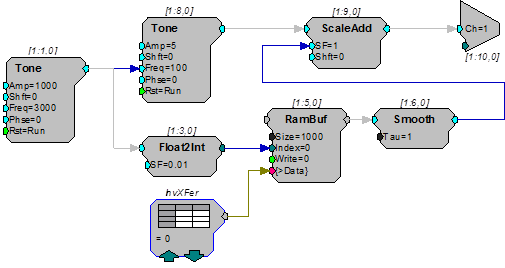
RAM Buffer - In this example we use a RamBuf component to map a frequency input to a modulator output. The Tone component at [1:1,0] modulates the frequency of the second Tone at [1:8,0]. The modulator frequency is also scaled and fed into the index input of the RamBuf allowing for a mapping from frequency to intensity scaling, which is held in the data table InvXFer. This type of circuit can be used to normalize a FM sweep for transducer variance across frequency.
ReadBuf
Description:
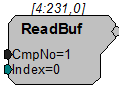
Gets a value from a specified memory buffer using a specified index. The buffer is specified by setting the CmpNo parameter to the component number of a RamBuf, SerialBuf, or AvgBuf component found within the circuit. The component number is the first number in parentheses found at the top of each component. The index number is the position within the buffer and must be set to a number less than or equal to the block size for the specified buffer.
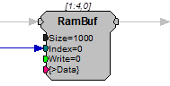
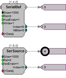
For example, to read a value from the RamBuf below, the ReadBuf CmpNo parameter is set to 4.
Important
Every time the circuit is even slightly modified, the component number of the required buffer might change. Always check the component number after recompiling. If the component number has changed update the ReadBuf component's CmpNo parameter, recompile, and recheck the component number.
SerialBuf
Description:
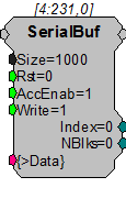
The SerialBuf component is a memory buffer manager with a built-in serial index generator. SerialBuf supports writing or reading, but does not support random access or simultaneous reading/writing. The Write control selects writing to (high) or reading from (low) the buffer and AccEnab triggers the read or write function. If AccEnable is high, the component will access the current index position in the memory buffer and the internal index generator is incremented. When the index reaches the total number of samples specified in the Size parameter it is automatically reset to zero and starts increasing again from there. Any data currently in the buffer will be written over.
Two outputs report the status of the SerialBuf component. The Index output reports the value of the internal serial index generator. The nBlks output counts the number of times the AccEnab input is enabled and disabled. This output can be thought of as a block counter.
Because SerialBuf requires that the AccEnable line remain high for each sample that is acquired, it is often used with the BlockAcc component. BlockAcc is enabled with a single enable pulse at the beginning of the block and then outputs an enable line that remains high for exactly the specified (BlkSze) number of samples.
Example:
Serial Buffer
File: Examples\SerialBuffer_ex.rcx
Default Processor: RP2 Processor
Sampling Rate: 50 kHz
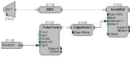
This circuit will compute the RMS level of channel one of the A/D input. When triggered via a zBus trigger, the RMS level will be written to the SerialBuf every 100 ms for 100 values. The EdgeDetect component makes sure that only one value is saved for each pulse out. The SerialBuf is 1000 points long, so the software trigger can be issued ten times before the buffer is full.
SerSource
Description:
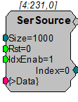
Implements a serial access memory function for playing a signal. When IdxEnab is set high the SerSource reads a value from the memory buffer, sends out the output, and increments to the next position in the buffer. The internal index generator is incremented until the total number of samples specified in the Size parameter has been read. When the index reaches the end of the memory buffer, it is automatically reset to zero and starts increasing again from there.
SerSource has several advantages over SerialBuf or RamBuf. It uses fewer cycles because it can only read from a buffer and users have direct control over the buffer size. Do not use SerSource if you need to both record and play or if you need to move to a particular position in the buffer.
When using SerSource, note that the first value loaded is ready for play out at index 0. When the enable line (IdxEnab) goes high with the first trigger, the index is incremented and the next value is sent to the SerSource signal output line. So, at index 1 the second value is played out. When SerSource is used to play out a list of individual values (such as a list of stimulus parameters) the first value sent to the SerSource might appear to be skipped. A Latch can be used to ensure that the output and index correspond more accurately to an ordered list of values. See "Comparing SerSource and SerialBuf Indexing and Output" below for more information.
Example:
SerSource
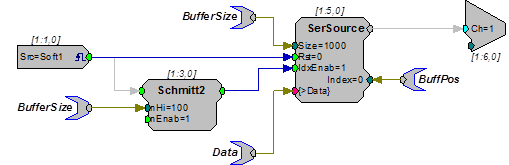
The example above shows a simple circuit that will play a signal out when a software trigger is generated. The BufferSize is fed to both the SerSource and to the Schmitt2 trigger (nHi). This ensures that there is no dead time for the signal out. The buffered signal is played out of the SerSource when the trigger goes high.
Comparing SerSource and SerialBuf Indexing and Output
When a circuit containing the SerSource component is run, the first value is loaded to the SerSource buffer, even if the enable line (IdxEnab) is low. When the enable line is triggered, the second value is loaded into the buffer, the index is incremented, and the second value is played out. This can sometimes give the appearance that the first value has been skipped, especially when individual values, such as a list of stimulus values, are being played out rather than a continuous waveform.
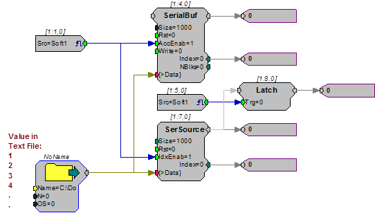
The simple circuit pictured below compares the output of the SerSource to that of the SerialBuf to demonstrate the differences in indexing and play out between these common components. In this example, the data in a SourceFile is fed to both the SerialBuf and SerSource. A simple software trigger is used to enable the buffers.
Circuit is loaded to the hardware...
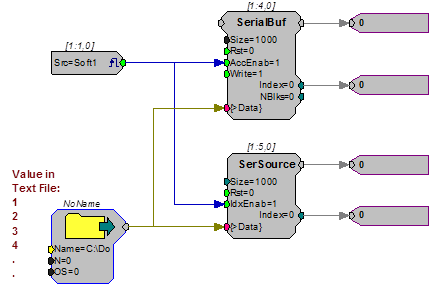
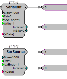
The values from the SourceFile are not yet ready for play out of either buffer.
Circuit is run... First software trigger...
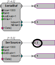
Second software trigger... Third software trigger...
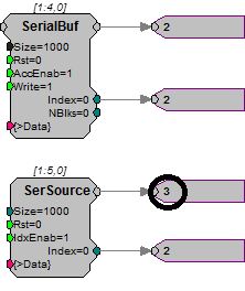
Using a Latch with SerSource
When using a SerSource, you can avoid the discrepancy between the index and the value accessed by adding a Latch that is triggered by the same trigger that triggers the SerSource enable line. This will latch the value loaded during the previous sample period so that the index and value number will match. In the example below, the earlier circuit has been modified to include a Latch.
Note
The same software trigger is used for the Latch and the buffer.
Circuit that is loaded to the hardware...
Circuit is run...
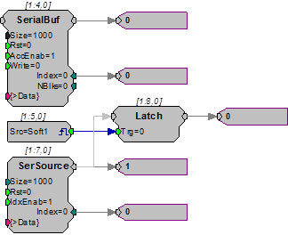
Although the first value from the SourceFile is already available for play out, the output of the Latch is still 0.
First software trigger...
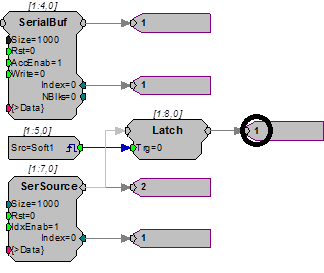
The second value has been loaded, but the output of the Latch is 1, the first value in the SourceFile.
Second software trigger...
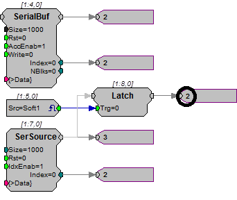
The output of the SerSource is 3 (the third value), but the output of the Latch is still 2.
Third software trigger...
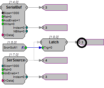
Here the index is 3 and the Latch output is 3, the third value in the SourceFile.
SerStore
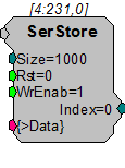
Description:
Implements a serial access memory function for storing data. The data port (>Data) provides access to the buffer so that it can be downloaded to the PC.
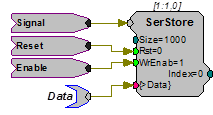
On each tick of the sample clock, when WrEnable is high, the SerStore reads a value from the input, stores it to the buffer, and increments to the next position in the buffer. The internal index generator is incremented until the total number of samples specified in the Size parameter have been written. When the index reaches the end of the memory buffer, it is automatically reset to zero and starts increasing again from there. Any data currently in the buffer will be written over.
SerStore has several advantages over SerialBuf or RamBuf. It uses fewer cycles because it is a write only buffer and users have direct control over the buffer size. Do not use SerStore if you need to both record and play or if you need to move to a particular position in the buffer.
Note for OpenEx users: When using with a data construct such as OxStream, the size of SerStore should be an even multiple of the block size of the construct.
Example:
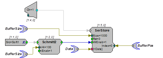
SerStore - The example below uses a parameter tag to generate the buffer size of the SerStore. The parameter tag also determines the duration of the Schmitt2 trigger (in samples). When a trigger is generated (Soft1) the Schmitt2 Trigger is enabled. This stores the number of samples specified by BufferSize to the SerStore. When the acquisition is finished the data can be downloaded to a PC from the >Data port.
SnipStore
Description:
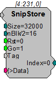
The SnipStore component stores multiple snippets of data to a buffer. The SnipStore was designed for use with the Tetrode component but can be used for any signal where the values before the trigger are important.
The SnipStore acquires a signal snippet based on the block size, nBlk/2 = X. When a logical high is detected, the store acquires nBlk/2-1 samples before the start of the trigger and nBlk/2-1 samples after the trigger. A Tag value is also stored at the start of each stored snippet. To avoid writing partial snippets, the snippet block size (nBlk) should always be a multiple of the buffer size (Size). The data port (>Data) provides access to the buffer so that it can be downloaded to the PC.
When used with a threshold detection circuit, SnipStore stores data with reference to the point at which a threshold is crossed. As shown in the figure below, it stores half the total number of points (specified as nBlk/2) before the threshold was crossed and half after that point.
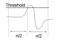
As a result, the point at which the threshold is crossed will always be centered in the acquired snippet. However, in many cases the threshold is not at the center of the signal of interest. For example, the portion of the signal of interest that occurs after the threshold is crossed may be longer than the portion of the signal that occurs before threshold is crossed. In these cases, the user must specify a block size that is larger than the expected length of the signal to ensure that the entire signal is stored.
Example:
See Tetrode, for an example of how the SnipStore can be used.
TagStore
Description:
TagStore was primarily designed for use in OpenEx and TDT macros. If used outside the OpenEx environment, be aware that the Tag input's data type may differ from the data type of the acquired waveform.
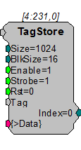
TagStore implements a serial access memory function for storing input data and is used to mark an acquired waveform with a scalar value such as a timestamp or other event code. On the first sample that both Enable and Strobe are high, storage of a block is initiated. TagStore stores the Tag value and the input value immediately. On each subsequent tick of the sample clock, when Strobe is high, the TagStore reads a value from the input, stores it to the buffer, and increments to the next position in the buffer. This continues until a full block of samples (defined by BlkSize) is stored, and then TagStore becomes ready to store the next block. When the index reaches the end of the memory buffer, it is automatically reset to zero. The data port (>Data) provides access to the buffer so it can be downloaded to the PC.
Data will be stored at the sampling rate of the DSP circuit if the Strobe input is always high. It can also decimate the incoming signal by providing a pulsed signal to the Strobe input. The period of the pulse determines how the signal is decimated.
Note
This component is for use with only high performance processor devices, such as RXn or RZn.
Note for OpenEx users: When using a data construct such as OxStream, the size of TagStore should be an even multiple of the block size of the construct.
Example:
In the example below, BlockAvg acquires 200 samples (set by the BlkSze parameter) of the input signal each time Trig goes high. Each block of 200 samples is summed with the current memory contents until 100 blocks have been acquired (set by the NumAvg parameter). The accumulated sum is output and WrEnable goes high to enable writing the data into the TagStore component with the Time HopIn component placing a time stamp on the data. AvgCnt outputs the current sample count and is reset to zero by a logic high on Reset.
WriteBuf
Description:
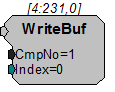
Writes a value to a specified memory buffer using a specified index. The buffer is specified by setting the CmpNo parameter to the component number of a RamBuf, SerialBuf, or AvgBuf component found within the circuit. The component number is the first number in parentheses found at the top of each component. The index number is the position within the buffer and must be set to a number less than or equal to the block size for the specified buffer.
For example, to write a value to the RamBuf below, the WriteBuf CmpNo parameter is set to 4.
Important
Every time the circuit is even slightly modified, the component number of the required buffer might change. Always check the component number (as shown in the figure below) after recompiling.
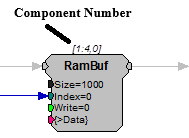
If the component number has changed update the WriteBuf component's CmpNo parameter, recompile, and recheck the component number.