Type Conversion
These Type Conversion components are used to convert a signal from one data type to another.
This group includes the following components:
This group also includes the following components, if RPvdsEx Device Setup is configured for a high performance device, such as the RXn or RZn:
- MCFloat2Int
- MCFloat2Int8
- MCFloat2Int16
- MCForceCC
- MCFromHop
- MCFromSer
- MCFromSing
- MCInsert4
- MCInt2Float
- MCInt16ToFLT
- MCInt8ToFlt
- MCMap
- MCMerge
- MCSubSel
- MCToSing
- MCToSer
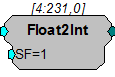
Float2Int
Description:
The Float2Int scales the input and converts the result from a 32-bit float to a 32-bit integer.
Equation:
Output = round(Input * SF)
Example:
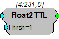
Float2TTL
Description:
This component returns 1 if the input is above the threshold value.
Equation:
If (Input > Thrsh) then Output = 1
else Output= 0
Example:
Flt2Stereo

Description:
Converts two floating point inputs into a stereo formatted signal.
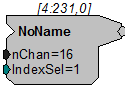
FromHopPick
Description:
FromHopPick outputs a single channel from an array of single channel indexed hops. Each hop must be named [Root]~# where [Root] is the name of FromHopPick and # is the channel number. There must be a hop for each channel. Use IndexSel to choose which hop to output from FromHopPick. See example below.
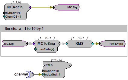
In this example, each channel of a 16-channel stream (MCSig) is extracted using MCToSing, the RMS computed and FromHopPick is used to access one channel for further processing. The RMS calculation occurs inside of an iterate box to simplify programming. This example is useful when MC components don't exist for the desired function.
Note
This component is for use with only high performance processor devices, such as RXn or RZn.
Int2Float
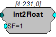
Description:
This component converts the input from a 32-bit integer to a 32-bit float and then scales the result.
Equation:
Output = Input * SF
Example:
Int2TTL
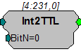
Description:
This component outputs 1 if the specified bit of the input is set.
Equation:
If (Input AND BitN) = 1, then Output = 1
else Output = 0
MCFloat2Int
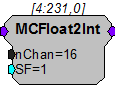
Description:
This is the multi-channel version of Float2Int. It scales the 32-bit floating point input of each channel and then converts the result to a 32-bit integer.
Note
This component is for use with only high performance processor devices, such as RXn or RZn.
Equation:
Output = round(Input * SF)
MCFloat2Int8
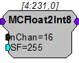
Description:
MCFloat2Int8 takes a multi-channel input of 32-bit floating values, scales them, converts them to 8-bit integer numbers and packs them into 32-bit integers. The resultant MC stream has nChan/4 channels.
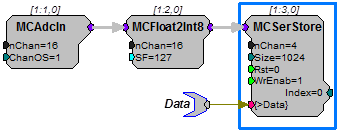
RPvdsEx might warn of a channel mismatch. It is okay to ignore this warning.
This reduction technique can be used to decrease memory allocation for data storage or quadruple the data transfer rate to and from the PC.
The scale factor (SF) is used to appropriately scale the floating point input before it is converted to an 8-bit integer. Use an SF of 127 for a ± 1V range and an SF of 12.7 for a ± 10 V range. The SF and input values must be matched. Mismatch between the SF and input value range gives poor resolution or meaningless data.
See Data Reduction and Scale Factor.
Note
This component is for use with only high performance processor devices, such as RXn or RZn.
MCFloat2Int16
Description:
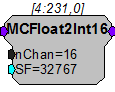
MCFloat2Int16 takes a multi-channel input of 32-bit floating values, scales and converts them to 16-bit integer numbers and packs them into 32-bit integers. The resultant MC stream has nChan/2 channels.
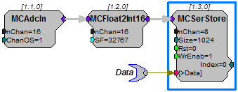
RPvdsEx might warn of a channel mismatch. It is okay to ignore this warning.
This reduction technique can be used to decrease memory allocation for data storage or double the data transfer rate to and from the PC.
The scale factor (SF) is used to appropriately scale the floating point input before it is converted to a 16-bit integer. The default SF is set to 32767 and assumes that the input is bounded between ± 1.0 V. Use an SF of 3276.7 for a ± 10 V range. The SF and input values must be matched. Mismatch between the SF and input value range gives poor resolution or meaningless data. See Data Reduction and Scale Factor.
Note
This component is for use with only high performance processor devices, such as RXn or RZn.
MCForceCC
Description:
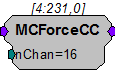
The MCForceCC component is used to force the in-path channel count to the specified value. This is useful for type conversions that inherently change the channel count (such as MCInt16ToFlt).
Note
This component is for use with only high performance processor devices, such as RXn or RZn.
MCFromHop
Description:
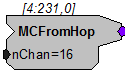
MCFromHop builds a multi-channel signal from single channel indexed hops. Each hop must be named [Root]~# where [Root] is the name of MCFromHop and # is the channel number. There must be a hop for each channel. See example below.
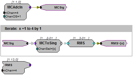
In this example, each channel of a four-channel stream (MCSig) is extracted using MCToSing, the RMS computed and the MC signal is reformed using MCFromHop. This occurs inside of an iterate box to simplify programming. This example is useful when MC components don't exist for the desired function.
Note
This component is for use with only high performance processor devices, such as RXn or RZn.
MCFromSer
Description:
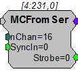
The MCFromSer component converts a serial sequence of integer or floating point values to a multi-channel signal. On each sample when SyncIn is high, the current input value is written to the current output channel pointer (starting with channel 1) and the channel pointer is incremented. To write all channels, SyncIn should go high for the total number of channels (nChan). When the last channel has been written to, the Strobe output will go high for one sample indicating that a new sample on each channel is ready. Each output value is latched until the next time it is updated.
Note
This component is for use with only high performance processor devices, such as RXn or RZn.
MCFromSing
Description:
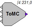
MCFromSing builds a multi-channel signal from multiple single channel signals. Most multi-channel components require merged multi-channel inputs. MCFromSing can be used to create a multi-channel signal using up to four single channels.
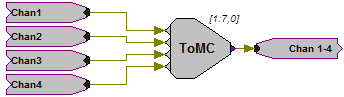
To build a multi-channel signal with more than four single channels, the signals must first be merged in groups of four using MCFromSing. The outputs from each MCFromSing can then be merged using the MCMerge. For higher channel counts or for a simplified technique, see MCFromHop.
Caution: Inputs to the MCFromSing must be of the same data type.
Note
This component is for use with only high performance processor devices, such as RXn or RZn.
MCInsert4
Description:
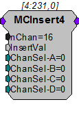
Insert a single-channel value on up to 4 channels of the multi-channel input stream. The selected channels (chosen by ChanSel-A...ChanSel-D) are overwritten with the value on the InsertVal input. This component is useful for generating stimulus for IZ2 that plays on a subset of channels. These can be cascaded to insert a value on more than 4 channels.
MCInt2Float
Description:
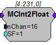
This is the multi-channel version of the Int2Float component. It converts the multi-channel input from 32-bit integers to 32-bit floating-point values and then scales the result.
Note
This component is for use with high performance processor devices, such as RXn or RZn.
Equation:
Output = Input * SF
MCInt16ToFlt
Description:
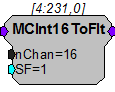
MCInt16ToFlt takes a multi-channel input of 32-bit integers where each 32-bit integer is packed with two 16-bit integers, scales and converts them to 32-bit floating point for further floating point processing. The input MC stream should have nChan/2 channels because of the integer packing. The output MC stream has nChan channels. This is the inverse operation of MCFloat2Int16.
Note
This component is for use with only high performance processor devices, such as RXn or RZn.
MCInt8ToFlt
Description:
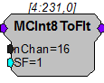
MCInt8ToFlt takes a multi-channel input of 32-bit integers where each 32-bit integer is packed with four 8-bit integers, scales and converts them to 32-bit floating point for further floating point processing. The input MC stream should have nChan/4 channels because of the integer packing. The output MC stream has nChan channels. This is the inverse operation of MCFloat2Int8.
Note
This component is for use with only high performance processor devices, such as RXn or RZn.
MCMap
Description:
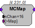
MCMap is a component that allows users to reorganize the input channel configuration to a desired output configuration. This allows the logical channel organization to match the spatial orientation of an electrode array. It can also be used to reorder TDT adapters to ZIF-Clip® headstages or EEG cap arrays.
Input channels from a MC component are reorganized based on the ordering of the channel number configuration from the >Map input parameter. The MCMap memory is an array equal in length to nChan that contains the reordered channels. For example, if recording channel eight of sixteen was the most distal electrode it could be remapped as either the first or last channel (channel 16).
Set nChan to the number of channels in the output signal (not the input signal). If nChan is smaller than the number of channels at the input a warning will be given in RPvdsEx, this warning may be disregarded if the intention is to output a subset of the multi-channel input signal.
Note
This component is for use with only high performance processor devices, such as RXn or RZn.
Example:
The example below illustrates how to remap the physical electrode sites of a 16-channel acute probe to the headstage.
A pinout of the headstage/adapter as well as the probe are required. The DataTable component in RPvdsEx can be used to load the channel map to the MCMap component.
Select ChanMap in the Type/Format drop down menu located in the DataTable component settings dialog when using the DataTable with the MCMap component.
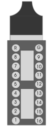
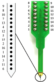
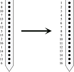
Headstage pinout 16-Channel Acute Probe and its site mapping.
Below is an example of the basic components used to remap the input signal.
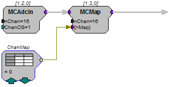
Based on the pinouts pictured above, the DataTable entries are mapped according to the desired position of the physical electrode sites. For instance, the most distal electrode on the acute probe is channel 6. If we wish this to represent channel 16, we would need to remap channel 6 to channel 16.
Since the headstage pinout matches the electrode, we only need to remap the electrode sites. After remapping the electrode sites according to their insertion depth from channel 1 to 16, the new physical site mapping will look like this:
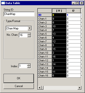
When the circuit is run, the first column is loaded.
Note
If you are not using the DataTable with the MCMap component, the channel map can be loaded as follows:
Map = 9 8 10 7 13 4 12 5 15 2 16 1 14 3 11 6
MCMerge
Description:
MCMerge merges multiple multi-channel signals to form a single multi-channel signal. The MCMerge inputs must be multi-channel signals. Single channel signals can be merged into a multi-channel signal using MCFromSing (ToMC). The MCMerge inputs may include any number of channels, so long as they are multi-channel signals.
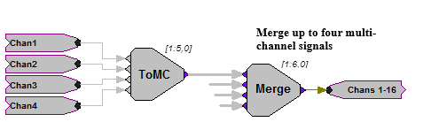
The MCMerge component is typically used to merge multiple channel signals from several MCFromSing components. If more than four channels are to be merged, they must first be merged in groups of four using MCFromSing. The outputs from each MCFromSing can then be merged using the MCMerge.
Note
This component is for use with only high performance processor devices, such as RXn or RZn.
MCSubSel
Description:
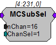
The MCSubSel is used to form a multi-channel signal from a sub-set of another multi-channel signal. Set nChan to the desired number of channels in the output signal (not the input signal). Set ChanSel to the first channel in the range of interest. ChanSel + nChan should not be greater than the number of channels contained in the input signal.
Note
This component is for use with only high performance processor devices, such as RXn or RZn.
Example:
To select channels 33 thru 48 of a 64 channel input signal, set nChan = 16 and ChanSel = 33.
MCToSer
Description:
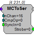
The MCToSer component serializes a multi-channel signal. It can be used for compressing high channel count sort code data and passing it across processors efficiently.
The rising edge of SyncIn is used to begin the conversion and should be pulsed once. The Strobe output goes high after SyncIn is triggered and remains high until the MC signal has been completely serialized. When Strobe is low, the output of MCToSer is nChan (or nChan + 1 if nChan is odd).
The CmpOp input determines the compression of the serial output. When CmpOp is 0, the serial stream is the same data type as the input stream. This is useful for serializing a data stream with a high precision (floats or 32-bit integers).
When CmpOp is 1, the serial stream contains nChan/2 values. The input stream should be unsigned integers with values in the range 0-15. Each output value contains data from two channels compressed into a single 32-bit value. The lower 16-bits of the first output contain the first channel data, the upper 16-bits of the first output contain the second channel, and so on.
When CmpOp is 2, the serial stream contains nChan/4 values. The input stream should be unsigned integers with values in the range 0-3. Each output value contains data from four channels compressed into a single 32-bit value. The lower 8-bits of the first output contain the first channel data, the next 8-bits of the first output contain the second channel, and so on.
Note
This component is for use with only high performance processor devices, such as RXn or RZn.
*See the component description for details of input/output data types as they correspond to the CmpOp value.
MCToSing
Description:
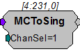
This component allows the user to extract a single channel signal from a multi-channel signal by selecting the channel number required. The channel number can be selected dynamically.
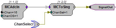
One MCToSing component is required for each single channel signal to be extracted. This component is particularly powerful when used with iterations.
Note
This component is for use with only high performance processor devices, such as RXn or RZn.
Example:
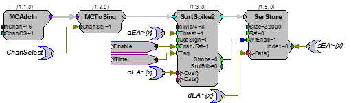
MCToSing - MCToSing is used to extract a channel for further processing using single-channel components. Typically, single channel signals must be extracted when there is no multi-channel component that can perform the necessary processing task. In the example below a single channel is extracted from a 16-channel signal, that channel is then processed for sorting spike data using SortSpike2.
Stereo2Flt

Description:
Splits a stereo input into separate Left and Right signals.
TTL2Float
Description:
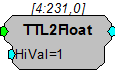
This component converts the input from a TTL value to the specified 32-bit float when true, else it converts the input to 0.
Equation:
If Input = 1, then Output = HiVal
else Output=0
TTL2Int
Description:
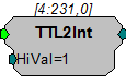
This component converts the input from a TTL value to the specified 32-bit integer when true, else it converts the input to 0.
Equation:
If Input = 1, then Output = HiVal
else Output = 0