NeuroAnalysis
The NeuroAnalysis components group includes the following components, developed primarily for neurophysiology applications:
This group also includes the following components, if RPvdsEx Device Setup is configured for a high performance device, such as the RXn or RZn:
BinRate
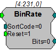
Description:
The BinRate component allows users to store or view spike rates. The Strobe output of a spike sorting component (or other pulse) is fed to the BinRate component's input to indicate a spike has occurred. At each falling edge of the input, the component uses the value of the SortCode parameter (an integer ranging from 0-3) to select and increment the count value of one of four internal bins. Each time reset goes high, the bin counts are latched to the output and then reset to zero. The output is a 32-bit integer with each byte representing a bin. The first eight bits store the values for SortCode 0 the next eight bits for SortCode 1 and so on.
Note
If the BinRate component receives more than 127 pulses in any bin in one interval, it will give erroneous results for that interval, as well as for all following intervals. TDT recommends using an update rate of 125 ms or less for the BinRate component.
The Bits output takes on one of four values (1, 2, 4, or 8) corresponding to the SortCode value at the falling edge of the input pulse. For example, if the SortCode is set to 3, the Bits output will be the integer 8 for one sample at the falling edge of the input.
Anomalies
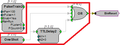
BinRate records one spike during each of the first two samples of running the circuit. The easiest work around is to ignore the first two spikes counted. However, if the circuit permits, you can add the circuitry shown in the example below to automatically reset the BinRate to ignore the two erroneous spikes.
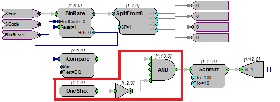
When a circuit is run, the Bits output will show a spike being detected, that is the output will go to 1, 2, 4 or 8 for the first and second sample clock tick, irrespective of whether a pulse came in or not. If the output is being used, it can be ANDed with NOT OneShot.
Example:
BinRate
In the example below, the BinRate component counts the number of spikes detected by SortSpike2, based on the SortCode value of each spike. The strobe output of SortSpike2 triggers the input of the BinRate component and the SortBits output is fed to the SortCode input.
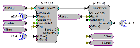
A PulseTrain2 resets the BinRate output once every two seconds. Therefore, the counts represent the number of spikes in each bin during a two second interval. The BinRate output is split into the counts for each bin by the SplitTo8 component.
The Bits output is used to light an LED every time a spike with the SortCode 0 (unsorted spikes in OpenEx) is detected. The components in the red blocks are temporarily needed for bugs.
FindSpike
Description:
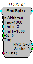
FindSpike detects spikes based on their deviations from the noise of the system. An RMS (root mean square) of the signal is calculated for a given time interval (Tau). Signal voltages that deviate by more than ThrLo and less than ThrHi deviations from the RMS are detected. The detector stores the waveform (nWidth in size) centered around its peak. The waveform along with a timestamp can be stored in a memory buffer.
Example:
FindSpike
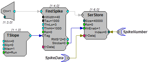
In the example above an analog input is sent to the FindSpike component. A TSlope is used to generate a timestamp. Data is saved to a SerStore (Note: the Strobe output is connected to the WrEnab line of the SerStore). Parameter tags allow ActiveX controls to access the spike data and spike number from the buffer. This FindSpike saves 39 points of data plus a timestamp tag (nWidth=40).
The Rst line allows the user to reset the FindSpike to the start of a candidate spike. This allows acquisition in a sweep based mode to only include spikes from the start of the sweep.
InstRate
Description:
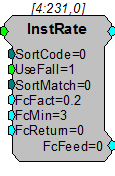
The InstRate (instantaneous rate) component acquires TTL inputs and converts each TTL pulse to a large floating point value. This value is then filtered through a low pass filter. The filtered value is then fed back into the InstRate component. Based on the input rate it either increases the filter (higher spike rates) or decreases the filter (lower spike rates) by a set value (FcFact) this value is then sent out the FcFeed parameter output to the input of the filter coefficient generator (Fc). Additional component features allow the signal to be generated on the falling edge of the TTL input or to use a SortCode.
Example:
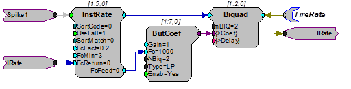
Instantaneous Rate - The example below shows how the InstRate component could be used to find the firing rate of neural activity. The logical output of the SortSpike Strobe is fed into the InstRate component where it is converted to a floating point value. A parameter tag allows ActiveX controls to access the firing rate from the Biquad.
Note
A loop warning will be displayed when the circuit is compiled; disregard this warning.
SampSubtract
Description:
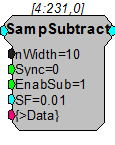
The SampSubtract component is useful for removing artifacts in the signal that are generated in a predictable manner (such as an artifact from electrical stimulation).
In order to remove the artifact, a signal snippet is acquired and added to a buffer during each occurrence of the artifact. A weighted fraction of the summed signal snippets is subtracted from the signal as each new artifact occurs. Over time the artifact will be removed from the signal with increasing accuracy and without reducing the integrity of the signal of interest.
Note
This component is for use with only high performance processor devices, such as RXn or RZn.
Accurate acquisition and removal of the artifact can only occur if the onset and length of the artifact are known and predictable. The Sync line is used to trigger acquisition, summing, and subtraction. So, the Sync input should be synced with the generation of the stimulus, and its duration should be set to the duration of the stimulus. Each time the Sync input goes high, SampSubtract acquires the snippet of signal for the duration of the Sync pulse and calculates the sum of snippets that is then weighted (multiplied by a fraction related to the Scale Factor) and subtracted from the input signal the next time that Sync goes high. The calculation of the weighted sum is related to the Scale Factor but also depends on the amplitude of the summed snippets.
Note
A delay may be required before the Sync input goes high to compensate for the time taken for the electrical stimulus to go through the outputs, into the brain, and back into the amplifier as an artifact.
When the circuit is run, the artifact will be gradually reduced as the weighted sum gradually increases. Hence, the signal will undergo a training period before the artifact rejection reaches an optimum level. The higher the value of Scale Factor, the shorter the training period, and the greater the chance of the useful part of the signal leaking into the weighted sum. Generally, a scale factor of 0.01 to 0.05 will provide good rejection results.
If the scale factor is set to 0, the summing stops, but the current weighted sum remains in the buffer, and continues to be subtracted from the signal. Setting the scale factor to 0 after the initial training period will continue the subtraction, but stop further growth of the subtracted signal reducing the likelihood that the useful signal around the artifact will be affected.
The nWidth parameter sets a predetermined buffer size to hold the weighted sum. It should be made sufficiently large to hold the summed signal.
The >Data pointer provides access to the weighted sum.
When the EnabSub input is high, the subtraction is enabled; when low, subtraction is disabled and the signal passes to the component output unaltered.
SortBin8
Description:
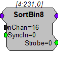
The SortBin8 component is useful for counting the number of sort codes per channel in a multi-channel signal. The input of the SortBin8 component is typically a multi-channel integer representing the sort code value for each channel. The output for each channel is a single 32-bit integer. Each byte in the integer contains the count for a single sort code making a total of four sort codes (1, 2, 3, and 4).
Sort Code:
On a rising edge of SyncIn, the sort code count for all channels is reset to 0. At this time the Strobe output simultaneously goes high for one sample to indicate that the count has been reset.
For example, suppose there are 7 spikes with sort code 1 and 9 spikes with sort code 2 since the last SyncIn. The output will be 231110 or:
Note
This component is for use with only high performance processor devices, such as RXn or RZn.
SortFlag16
Description:
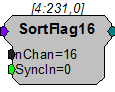
SortFlag16 is useful for monitoring sort code activity over a period of time. The SortFlag16 component flags two sort codes for each channel based on its multi-channel input signal (which will most likely come from a SpikePac power macro sort code output). SortFlag16 polls each input channel for a value of 1 or 2, if either value exists on any channel, SortFlag16 sets the corresponding flag bit to a logic high (1). On the rising edge of SyncIn , SortFlag16 latches a 32-bit integer value which contains two flag bits for each channel (each flag represents a sort code of 1 or 2).
The SortFlag16 output structure for the 32-bit integer is shown below.
Channel Sort code
After SyncIn has detected a rising edge it resets the internal flags for each channel.
For example, you are sending a rising edge to the SyncIn input every 10 ms. Sort code values of 1 and 2 are sent to channels 1, 3, and 5 between the last rising edge of SyncIn. On the next rising edge of SyncIn, the output will be 81910 or:
Note
This component is for use with only high performance processor devices, such as RXn or RZn.
SortSpike
Description:
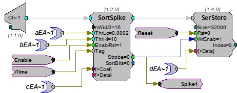
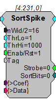
The SortSpike component sorts spikes using a time/voltage window discriminator. The threshold voltage (window) is selected with the ThrLo and ThrHi parameters. When a candidate waveform is detected it is tagged with the value from the Tag input and a sort value is assigned (SortBits). The data output contains the Tag value (timestamp), sort value (sort code) and the waveform. The waveform is stored with the peak of the spike centered in the data buffer. For more information see the OpenEx Manual .
Organization of Waveform Data
Sample 1 = Tag Value (Timestamp)
Samples 2: (n-1) = Waveform
Sample n = Sort code
Sample n/2 = Waveform Peak
For a SortSpike with nWid/2 = 16 the number of waveform samples would be 32-2 (Tag and SortBit) or 30 points of signal waveform. The peak would be at sample 15.
This component is used primarily by TDT turnkey applications such as OpenEx. Users should read the description of how to use SortSpike in OpenEx. A description of how to use the component with custom codes is described below.
Setting the Time-Voltage and Sort Codes via Custom Software
The SortSpike component uses information stored in a coefficient vector to determine the time-voltage and sort code values.
Organization of the coefficient vector is as follows:
The coefficients are organized into a vector array which is 3 times the length of the waveform. Three consecutive indices in the vector are associated with a single sample along the waveform. These three values define a time-voltage window discriminator or 'hoop' that a given waveform may pass through.
This means that vector indices [0], [1], and [2] represent the three time-voltage hoop characteristics for the first sample of the waveform.
The three values used to define a hoop are the Center Voltage, Half-Height Voltage, and Sort Code.
The Center and Half-Height Voltages are specified in Volts while the Sort Code is specified as a positive integer from 1 to 30.
Note
If the incoming waveform passes through more than one hoop, the hoop in which the waveform passes closest to the Center Voltage determines which hoop's Sort Code gets assigned.
Samples not containing hoops must have all three hoop characteristics zeroed.
For Example, a waveform containing 8 samples will use a coefficient vector with a length of 24. If we wish to have two hoops, one at waveform position 3 and another at waveform position 6, the coefficient vector to be loaded would be:
0 0 0 0 0 0 C1 H1 S1 0 0 0 0 0 0 C2 H2 S2 0 0 0 0 0 0
Where:
C1, H1, and S1 are the Center Volt, Half-Height Volt, and Sort Code values for Hoop 1
C2, H2, and S2 are the Center Volt, Half-Height Volt, and Sort Code values for Hoop 2
Users can upload the vector to the component's coefficient parameter. A simple path for using this setup would require that candidate waveforms be downloaded to the PC. Users would then view the plotted waveforms and determine the time in samples and voltage position that would differentiate two classes of waveforms.
SortSpike2
Description:
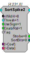
The SortSpike2 component sorts spikes using a time/voltage window discriminator. Candidate waveforms are detected when the rising edge (positive waveforms) or falling edge (negative waveforms) of the waveform crosses the threshold voltage (window) set for the Thresh parameter. The UseSign parameter allows the user to specify unidirectional or bidirectional waveform detection. When a candidate waveform is detected it is tagged with the value from the Tag input and a sort value is assigned (SortBits). The data output contains the Tag value (timestamp of rising or falling edge), sort value (sort code) and the waveform. The waveform is stored with the point at which the rising or falling edge crosses the threshold at nWid/4 samples. For more information see the OpenEx Manual .
Organization of Waveform Data
Sample 1 = Tag Value (Timestamp)
Samples 2:(n-1) = Waveform
Sample n = Sort Code
For a SortSpike2 with nWid/4 = 16 the number of waveform samples would be 64 - 2 (Tag and SortBit) or 62 points of signal waveform.
This component is used primarily by TDT turnkey applications such as OpenEx. Users should read the description of how to use SortSpike2 in OpenEx. A description of how to use the component with custom codes is described below.
Setting the Time-Voltage and Sort Codes via Custom Software
The SortSpike2 component uses information stored in a coefficient vector to determine the time-voltage and sort code values.
Organization of the coefficient vector is as follows:
The coefficients are organized into a vector array which is 3 times the length of the waveform. Three consecutive indices in the vector are associated with a single sample along the waveform. These three values define a time-voltage window discriminator or 'hoop' that a given waveform may pass through.
This means that vector indices [0], [1], and [2] represent the three time-voltage hoop characteristics for the first sample of the waveform.
The three values used to define a hoop are the Center Voltage, Half-Height Voltage, and Sort Code.
The Center and Half-Height Voltages are specified in Volts while the Sort Code is specified as a positive integer from 1 to 30.
Note
If the incoming waveform passes through more than one hoop, the hoop in which the waveform passes closest to the Center Voltage determines which hoop's Sort Code gets assigned.
Samples not containing hoops must have all three hoop characteristics zeroed.
For Example, a waveform containing 8 samples will use a coefficient vector with a length of 24. If we wish to have two hoops, one at waveform position 3 and another at waveform position 6, the coefficient vector to be loaded would be:
0 0 0 0 0 0 C1 H1 S1 0 0 0 0 0 0 C2 H2 S2 0 0 0 0 0 0
Where:
C1 , H1 , and S1 are the Center Volt, Half-Height Volt, and Sort Code values for Hoop 1
C2 , H2 , and S2 are the Center Volt, Half-Height Volt, and Sort Code values for Hoop 2
Users can upload the table to the component's coefficient parameter. A simple path for using this setup would require that candidate waveforms be downloaded to the PC. Users would then view the plotted waveforms and determine the time in samples and voltage position that would differentiate two classes of waveforms.
SortSpike3
Description:
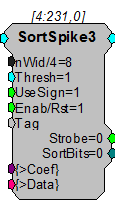
The SortSpike3 component sorts spikes using a time/voltage window discriminator. Candidate waveforms are detected when the rising edge (positive waveforms) or falling edge (negative waveforms) of the waveform crosses the threshold voltage (window) set for the Thresh parameter. The UseSign parameter allows the user to specify unidirectional or bidirectional waveform detection. When a candidate waveform is detected it is tagged with the value from the Tag input and a sort value is assigned (SortBits). The data output contains the Tag value (timestamp of rising or falling edge), the waveform and sort value (sort code). The waveform is stored with the point at which the rising or falling edge crosses the threshold at nWid/4 samples.
SortSpike3 is a slight modification to the SortSpike2 component. The only difference is in the determination of the sort code.
Organization of Waveform Data
Sample 1 = Tag Value (Timestamp)
Samples 2:(n-1) = Waveform
Sample n = Sort Code
For a SortSpike3 with nWid/4 = 16, the number of waveform samples would be 64. This number includes 62 points of signal waveform, the tag value and sort code.
This component is used primarily by TDT turnkey applications such as OpenEx. Users should read the description of how to use SortSpike3 in OpenEx. A description of how to use the component with custom codes is described below.
Setting the Time-Voltage and Sort Codes via Custom Software
The SortSpike3 component uses information stored in a coefficient vector to determine the time-voltage and sort code values.
Organization of the coefficient vector is as follows:
The coefficients are organized into a vector array which is 3 times the length of the waveform. Three consecutive indices in the vector are associated with a single sample along the waveform. These three values define a time-voltage window discriminator or 'hoop' that a given waveform may pass through.
This means that vector indices [0], [1], and [2] represent the three time-voltage hoop characteristics for the first sample of the waveform.
The three values used to define a hoop are the Center Voltage, Half-Height Voltage, and Hoop Number.
The Center and Half-Height Voltages are specified in Volts while the Hoop Number is specified as a positive integer.
Samples not containing hoops must have all three hoop characteristics zeroed.
For Example, a waveform containing 8 samples will use a coefficient vector with a length of 24. If we wish to have two hoops, one at waveform position 3 and another at waveform position 6, the coefficient vector to be loaded would be:
0 0 0 0 0 0 C1 H1 N1 0 0 0 0 0 0 C2 H2 N2 0 0 0 0 0 0
Where:
C1 , H1 , and N1 are the Center Volt, Half-Height Volt, and Hoop Number values for Hoop 1
C2 , H2 , and N2 are the Center Volt, Half-Height Volt, and Hoop Number values for Hoop 2
If the incoming waveform passes through more than one hoop, each hoop sets a corresponding bit in the final sort code by the relationship:
2(HoopNum-1)
For example, if an incoming waveform passes through hoops 1,2 and 3, the following bits would be set:
Value Bit
2(1-1) =1 0
2(2-1) =2 1
2(3-1) =4 2
This results in a final sort code of 7.
Users can upload the table to the component's coefficient parameter. A simple path for using this setup would require that candidate waveforms be downloaded to the PC. Users would then view the plotted waveforms and determine the time in samples and voltage position that would differentiate two classes of waveforms.
Note
This component is for use with only high performance processor devices, such as RXn or RZn.
Tetrode
Description:
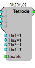
The Tetrode component is designed to synchronize the acquisition of snippets from multiple channels. Trigger inputs (Thr1-4) set the voltage threshold for each channel of the tetrode. When the signal from a channel crosses its threshold a TTL pulse is generated. The TTL output can be sent to a Block Access (with a delay) or it can be used to trigger a SnipStore component that saves the waveform and stores a time stamp.
Tetrode and SnipStore are designed primarily for use with the OpenEx software suite. To learn more about how to use the Tetrode and SnipStore components with OpenEx check your OpenEx documentation.
Note
This component is for use with only high performance processor devices, such as RXn or RZn. If you are using a Classic Processor, see the examples below for an alternative circuit design or contact TDT technical support for more information.
Example:
Tetrode
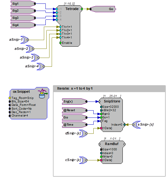
The example below shows how the basic Tetrode component could be used in OpenEx. The Tetrode component compares signals from four input channels to a corresponding voltage threshold. When a threshold is reached on any of the four channels, the Tetrode output sends out a pulse for one cycle.
This output pulse (Go) can then be used to trigger the buffer acquisitions which iterate four times, 1 for each channel. Each signal can be acquired with a SnipStore that stores n/2 samples before and after the trigger as well as a time stamp (Tag). Since each channel of the buffer would have the same number of stored values only one Index needs to be polled. The use of "cSnip~{x}" with a RamBuf allows threshold controls in OpenController.
This example illustrates an alternative circuit design to achieve a signal equivalent to the output of the Tetrode component without using the component itself. This example is for users who wish to achieve the same operation as Tetrode using lower order components on a Classic Processor.
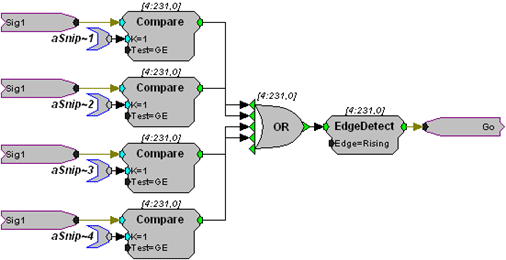
The corresponding voltage threshold for each input channel can be controlled by modifying the aSnip~ tag value tied to the K parameter of each Compare component.