Counters and Logic
The Counters and Logic components are used primarily for program control. They often control the activity of individual components via trigger or enable inputs.
This group includes the following components:
- And
- AndOr
- Counter
- DeBounce
- EdgeDetect
- JKFlipFlop
- Not
- OneShot
- Or
- PulseTrain
- PulseTrain2
- PulseTrain3
- RSFlipFlop
- Schmitt
- Schmitt2
- TTLDelay
- TTLDelay2
- Xor
And
Description:
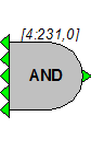
Logical AND function. Returns 1 (true) if all inputs are 1 (true). All multiple inputs must be from a primary output. If it is necessary to route a parameter output to this function use a ConstL to make it a primary output.
Equation:
Lo = AND (Li1, Li2, Li3, Li4, Li5)
Example(s):
AND (0, 0, 0, 1, 0) = 0 (false)
AND (1, 1, 1, 1, 1) = 1 (true)
AndOr

Description:
Logical AND/OR function. Returns 1 (true) if input and AndIn parameter are 1 (true), or if OrIn parameter is 1 (true). If it is necessary to route a parameter output to this function use a CONSTL to make it a primary output.
Equation:
Lo = (Li AND AndIn) OR OrIn
Example(s):
On each tick of the sample clock the following truth-table applies:
Counter
Description:
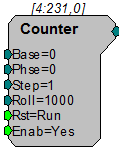
The Counter is a count up/down counter. It counts for as long as a high pulse is going to the enable port (Enab). It increments the count by a set value (determined by Step) for each pulse of sample clock (e.g. if the enable is high for 1 msec and the sample rate is 25 kHz then the counter will step 25 times). Once it exceeds the sum of the Base and Roll value the Counter starts counting again at the base value (Base) (see below for more details). The first time the counter is started or after the Reset (Rst) port has been triggered (value goes from low (0) to high (1)) the Counter starts at the Base value plus the Phase (Phse) value.
The example below shows many of the features of the Counter.
Example parameter settings are: Base = 8, Phse = 11, Step = 2, Roll = 20.
The Counter sequence begins at the Phse value when the circuit is first run: the initial count value output is therefore 11.
The count value on progressive samples would be incremented by Step = 2:
13, 15, 17, 19, 21, 23, 25, 27
The Roll and Base values determine the value at which the counter rolls over.
Since Base = 8 and Roll = 20, the counter will roll over when its count value is incremented to a value greater than or equal to 28 (8 + 20). During a rollover, the remainder of the Step value is carried over.
Recall that our last counter value output was 27. As the counter increments this value to 29 there is a remainder of 1 prior to the rollover (29 - 28). This remainder is added to the Base value and output on the following sample.
Since Base = 8 the new counter value output will be 9 (8 + 1).
The counter will then be incremented by Step for each progressive sample until the rollover value is encountered. The sequence will repeat as long as Enab is high and Rst is not triggered.
Tech Notes
The Counter is incremented for each tick of the sample clock.
Phse only functions when the Enab first goes high or after Rst is triggered. As long as Rst is high (1) the count value remains at the Base + Phse.
All Components of the Counter are available while the RP2 chain is running.
To use the Counter as a Count down circuit the Base value must be less than the roll value. When the Counter reaches the Base value it Rolls over to the Roll value and repeats the count down.
The Counter does work properly when Rst is less than zero.
The Base value can be negative only if Roll and Step are positive values.
Example:
WordIn-WordOut, Working with WordIn - WordOut.
DeBounce
Description:
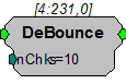
A DeBounce filters out transient changes in input. The output of the signal is tied to the input. When the input changes and remains constant for a set number of samples the output switches. If the input switches state during the sampling period the output does not change.
EdgeDetect
Description:
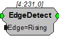
This component returns true for one cycle of the sample clock when the specified edge (rising or falling) is encountered. It is useful for converting a TTL to a single sample high. The edge direction cannot be changed once the processing chain is started. Note: When Edge is Falling, the output will be true on the first sample.
Edge = Rising or Falling (goes high either on rising or falling edge (static))
Example(s):
Block Access (example with trigger), BlockAcc.
Serial Buffer (example with PulseTrain), SerialBuf.
JKFlipFlop
Description:
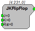
Implements a standard J-K flip-flop. See truth table below.
Equation:
On each tick of the sample clock the following truth-table applies:
Not

Description:
Inverts signal logic, i.e. changes 0's to 1's and 1's to 0's.
Equation:
Lo = NOT (Li)
OneShot
Description:
Generates a single TTL output when chain is first run.
Equation:
Lo = 1, first sample only. Otherwise Lo = 0
Or
Description:
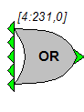
Logical OR function. Returns 1 (true) if any input is 1 (true). All multiple inputs must be from a primary output. If it is necessary to route a parameter output to this function use a CONSTL to make it a primary output.
Equation:
Lo = OR (Li1, Li2, Li3, Li4, Li5)
Example(s):
OR (0, 0, 0, 0, 0) = 0 (false)
OR (0, 0, 0, 1, 0) = 1 (true)
OR (1, 1, 1, 1, 1) = 1 (true)
PulseTrain
Description:
This component generates a pulse train, i.e. a series of pulses with specified times for a high (1) and low pulse (0).
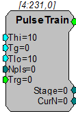
When externally triggered (via Trg) with a low (0) to high (1) pulse, the rising edge of trg, the PulseTrain component sends out a number of pulses (Npls (positive integer)). Each pulse will go high for a set time (Thi Time High (in milliseconds)). The pulse then goes low for a set time (Tlo Time Low (in milliseconds)). After all pulses have been sent PulseTrain waits for another Trigger (Trg).
The signal output will be high for the (Thi-Tg) milliseconds and then low for Tlo milliseconds. The Tg parameter can be used when the PulseTrain is driving a signal gate.
Two parameters (Stage and CurN) are used to determine the status of PulseTrain. Stage determines if PulseTrain is waiting for a Trigger (Stage=0), is sending a high pulse (Stage =1) or a low pulse (Stage=2). Current Number (CurN) determines how many pulses remain.
For example the values in the picture above would generate the following response: On a trigger from low to high (Trg) the pulse train would send out 5 pulses each with a 99.75 msec high (100 (Thi)-0.25(Tg)) and a 100 msec low (Tlo).
Tech Notes
PulseTrain responds to the rising edge of a trg.
Setting Npls = 0 produces a continuous series of pulses. When Npls = 0 CurN counts down from 0 (produces negative values).
A Schmitt Trigger performs a similar operation, but differs in a variety of ways such as it has 1) no gate time, 2) a single pulse, 3) detects high state rather than rising edge.
All components of a PulseTrain can be accessed while the RP2 chain is running.
The PulseTrain ALWAYS is triggered by going from low to high regardless of the Trg value.
Pulse minimum Thi is two ticks of the sample clock. This is true even when Thi = 0
Minimum for Tlo = 0
Example:
Averaged Buffer (generating a pulse train to trigger a signal), AvgBuf.
PulseTrain2
Description:
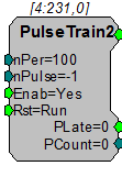
PulseTrain2 sends out a TTL pulse (one cycle) every nSamples (nPer). The number of pulses generated is set with nPulse. While the Enab line is high (1) the PulseTrain2 counts up to the number of pulses. When the Enab line goes low the PulseTrain2 is locked at the last nPulse, unless Rst is triggered. Rst resets the number of pulses generated (Pcount) to zero.
Tech Notes
Rst resets the counter even while the system is enabled.
If the Enab line and the Rst line are set high, PulseTrain2 still generates TTL pulses.
The nPer (number of samples between pulses) and the nPulses (number of pulses) can be changed while the PulseTrain2 is enabled. However, this can cause problems if the nPulses is less than the number of pulses generated.
Setting nPulse to -1 generates a continuous number of pulses.
Example:
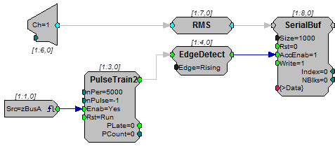
PulseTrain2 - In this example a TTL pulse is generated every 5000 samples. Each time a pulse is generated the RMS signal from A/D channel 1 is stored into a memory buffer. To start and stop the acquisition a zBUS trigger is generated. The zBUS trigger is used because it can be set always high or low, unlike the software triggers that stay high for a single pulse.
PulseTrain3
Description:
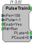
In contrast to PulseTrain2 (see above), PulseTrain3 latches the input parameters when Rst is triggered. This allows you to adjust the nPer parameter on the fly for the next stimulation period without interrupting the current stimulus.
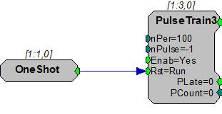
By default the output will not start when the circuit starts, it is waiting for the Rst input to be triggered at least once. For continuous trains, you can use the OneShot component to trigger it at the start of the circuit.
RSFlipFlop
Description:
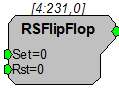
Simple set/reset flip flop similar to an on/off light switch. Set turns on the switch (makes it high) when triggered by a high pulse. Rst turns the switch off when it is triggered by a high pulse. If both Set and Rst are 0 then the output is not altered (switch either stays On or Off).
Equation:
Output = 0 when Rst = 1
Output = Output(t-1) when Set=0 and Rst = 0
Output = 1 when Rst = 0 and Set = 1
Schmitt
Description:
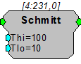
This component performs a Schmitt trigger. If a logical high is detected, the output goes to a high state for a set amount of time (determined by Thi ). At the end of the high time, the output goes to a low state for a set time (determined by Tlo ). Once that time has expired, the Schmitt can be triggered again.
Tech Notes
If the input to the Schmitt trigger is high(1) at the end of the cycle ( Thi + Tlo ) a new pulse is sent out. This is in contrast to PulseTrain that responds only to a rising edge of a trigger.
By setting Tlo to zero the Schmitt trigger is immediately ready for another trigger event.
The minimum time high ( Thi ) is two ticks of the sample clock.
It has a lower cycle usage compared to a PulseTrain.
Equation:
If (Li ) then
From t=0 to Thi, Lo=1
From t=(Thi +1) to Tlo, Lo=0
Schmitt2
Description:
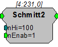
This component performs a Schmitt trigger. If a logical high is detected, the output goes to a high state for a set number of samples (determined by nHi). Once that time has expired, the Schmitt2 component can be triggered again.
Tech Notes
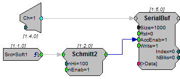
The Schmitt2 trigger is excellent for storing a set number of samples to a buffer.
Equation:
If (Li) then
From s=0 to nHi if nEnab=1, Lo=1
else Lo=0
Example:
Schmitt2 - Acquire 100 samples of a signal.
TTLDelay
Description:
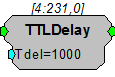
This component looks for the rising edge of the input and generates a TTL for a single sample after the specified delay. This function is useful if two signals are to be triggered with a short delay between them.
TTLDelay2
Description:
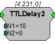
When the input to this component is a logical 1, the output is a pulse train that is logic high for one sample and low for N1 + N2 - 1 samples. This pulse train is also delayed from the onset of the input by N1 + N2 samples. This is different than TTLDelay which sends out one pulse after each rising edge of the input (see figure below). The total delay is specified by N1 + N2 samples, however, depending on the application, N2 may be zero.
Note
No pulses are sent if N1 and N2 are both set to zero. Ensure that you have at least a 1 entered for either N1 or N2.
The following figure shows the output of the TTLDelay2 component compared to that of TTLDelay.
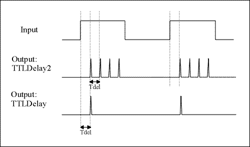
If an EdgeDetect (Edge=Rising) precedes TTLDelay2 in a circuit, the output of TTLDelay2 is similar to that of TTLDelay.
Xor
Description:
Logical XOR function. Returns 1 (true) if only one input is 1 (true). All multiple inputs must be from a primary output. If it is necessary to route a parameter output to this function use a ConstL to make it a primary output.
If more than two inputs are used, the XOR function steps through from top to bottom.
Equation:
Lo = XOR (Li1, Li2, Li3, Li4, Li5)
Examples:
XOR (0, 0) = 0 (false)
XOR(1, 1) = 0 (false)
XOR (0, 1) = 1 (true)
XOR (1, 0) = 1 (true)
Note
If more than two inputs are used, the XOR function steps through from top to bottom.
XOR (1, 1, 1, 1, 1) = 1 (true)
For this example the XOR function evaluates the inputs two at a time.
1 (1st input) XOR 1 (2nd input) = 0
0 (result of 1st and 2nd) XOR 1 (3rd input) = 1
1 (result of 1st , 2nd , and 3rd input) XOR 1 (4th input) = 0
0 (result of other 4 inputs) XOR 1 (5th input) = 1