State/Flow Control
The StateFlow Control group includes components for the StateFlow control functions.
This group includes the following components:
This group also includes the following component, if RPvdsEx Device Setup is configured for a high performance device, such as the RXn or RZn:
MCSampHold
Description:
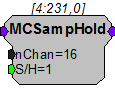
The MCSampHold component is the multi-channel version of the SampHold component. It samples input values while S/H is set to a logical high. When S/H goes to zero, the last value is held. MCSampHold differs from Latch in that Latch holds the first value when triggered by a logical high input and holds that value until the next logical high.
Example:
Multi-channel Sample and Hold
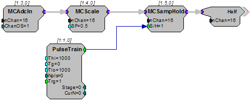
The above example uses a MCSampHold component to look at the scaled value of the multi-channel input from the ADC every 2000 milliseconds. The S/H parameter is set high for 1000 ms and set low the rest of the time, so it samples for 1000 milliseconds and then holds the last value for 1000 milliseconds.
MuxIn
Description:
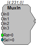
Multiplexer device. Takes four input streams and sends one of them to its output. The select parameter indicates which input is sent to the output. Reset sets the output value to zero. See "MuxOut" below.
Equation:
Lo = Ii, i=Select value
MuxOut
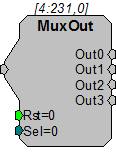
Description:
Multiplexer device. Takes one input and sends it to one of four outputs. The select parameter determines which output stream is chosen. Unselected outputs are set to zero. Reset sets all outputs to zero. See "MuxIn" above.
Equation:
Lo = Ii, i=Select value
SampHold
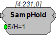
Description:
The SampHold component Samples input values while S/H is set logical high. When S/H goes to zero the last value is held. SampHold differs from Latch in that Latch holds the first value when triggered by a logical high input and holds that value until the next logical high.
Example:
Sample and Hold
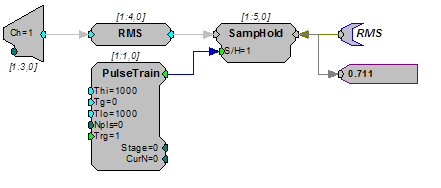
The above example uses a SampHold component to look at the RMS value of the input from the ADC every 2000 milliseconds. The S/H parameter is set high for 1000 ms and set low the rest of the time, so it samples for 1000 milliseconds and then holds the last value for 1000 milliseconds.
SimpCount
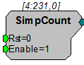
Description:
The SimpCount component is a simple counter that starts at zero and counts up from there. The count goes up by one for each sample period that the Enable parameter is set high. If the Reset parameter is set high, the count gets reset to zero.
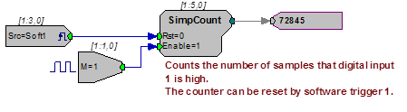
The Counter component is more powerful than SimpCount, and allows for different starting values, looping, etc. SimpCount is useful for basic counting tasks, but Counter is required for more advanced counting tasks such as offsetting the position in a memory buffer.
StateMach
Description:
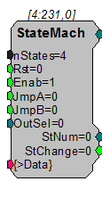
A state machine changes its output based on the combination of inputs to the system. A look-up table (see example below) determines the state of the machine. An additional Output select table allows the user to send a given output based on the machine's state.
The state machine is divided into two parts. The first part determines the state of the machine and the second part determines the output value.
Determining The State Of The Machine.
Four inputs determine the state of the machine.
When Reset is high (=1) the machine state becomes state 0.
When Enable is low (=0) the machine state is fixed at the last state until it goes high again (=1).
When Enable is high (=1) and Reset is low(=0) the state of the machine is determined by the input values for JmpA and JmpB. The top portion of the look-up table (see example below) determines the state based on the present state of the machine and the input values for JmpA and JmpB.
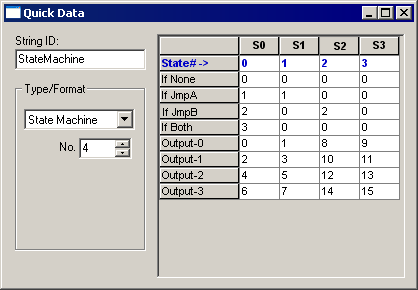
Using the example below: if the last state of the machine was State 2, (JmpB=1) and JmpA went high (=1) the state machine would go to state 0 (In state 2 when both JmpA and JmpB are high (=1) the state of the machine becomes State 0). It then becomes State 3 (When Both=1 in State 0 the State changes to State 3). After that it toggles between state 3 and state 0.
Use StNum to check the present state of the Machine.
Use StChange to check if the state of the machine has changed.
Determining The Output Of The State Machine.
The Output select (OutSel) value (in conjunction with the machine state) determines the output value of the State machine.
In the look-up table example below when machine is in State 1 (S1) and the OutSel=3 the Output value is the integer 7.
Use DataTable to design the look-up table. Below is the logical structure for a look-up table. In the table below, the columns S0, S1, S2, and S3 correspond to the four possible states of this state machine. The logic rows (If None, If JmpA, If JmpB, If Both) are used to control how the state machine jumps from one state to another. The Output rows are used to control the output of the state machine, depending on the OutSel input and the current state.
Note
The state machine outputs only integers.