Multi-Channel Circuit Design
Overview
In a typical multi-channel application most, if not all, channels will be processed in the same way. The user can take advantage of this fact by using multi-channel components and multi-channel macros wherever possible. These components and macros have been designed specifically for multi-channel processing and are more efficient than their single channel counterparts. When neither multi-channel components nor a multi-channel macro is available for a particular processing task, iterations can be used to simplify the parts of the circuit that must use single channel components.
When designing multi-channel circuits the user should keep in mind that:
- Simplifying circuit design makes debugging or modifying the circuit easier.
- Using the most efficient components possible improves performance and ensures that all processing tasks can be accomplished without overtaxing the processor or exceeding the maximum number of components allowed.
- Using macros reduces the overall number of parameter and configuration settings required while reducing the likelihood of channel number or data type mismatches.
Note
Multi-channel components can only be used with high performance devices, such as the RX and RZ devices. Circuits that implement them will not run on single processor systems, such as the Medusa RA16BA. However, the iteration function can be used by all devices to streamline circuit design. Macros that use multi-channel components typically include "MC" in the macro name. See the reference for your device for specific information on component compatibility.
The Nature of Multi-Channel Signals
A multi-channel signal is an array of data points arranged according to channels. On each tick of the sample clock, the multi-channel component processes one point from each channel.
Working with Multi-Channel Components
Multi-channel components are a powerful group of components for working with multi-channel signals. When working with these components the user must carefully consider the number of channels and type of data in the multi-channel data stream.
Data Types
Most multi-channel components accept any data type as input. No error will be generated if the signal output from one component is linked to a component input that requires another data type. Therefore, the user must ensure that data types are consistent.
nChan Parameter
Multi-channel components can be used to process multi-channel signals from four to 256 channels. Many multi-channel components include a channel number (nChan) parameter that must be set at design time, to the number of channels in the multi-channel signal input. Mismatched channel number parameters may cause warnings, but will not cause errors when the circuit is compiled. Therefore, the user must ensure that the channel number parameter is set correctly.
Multi-Channel Circuit Design Strategies
The best circuit design for multi-channel circuits maximizes the use of multi-channel components and multi-channel macros while minimizing the number of conversions between multi-channel components and single channel components. This path has several advantages. Multi-channel components use fewer cycles, and require fewer components to accomplish processing tasks for multiple channels. Also, multi-channel components and macros help to keep circuit design cleaner, more manageable, and easier to debug. Macros help eliminate common multi-channel errors, such as mismatched data types and mismatched number of channels.
This section provides general guidelines for multi-channel circuit design by taking the user through the process of building commonly used circuit segments.
Acquisition
Users must consider their hardware configuration when designing an acquisition circuit.
The RZ2 Processor
The RZ2 is equipped with several different analog I/O capabilities. Two types of fiber optic ports allow a direct connection to Z-Series or Medusa Preamplifiers. The RZ2 also includes onboard A/D for input of signals from a variety of other analog sources.
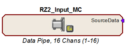
The RZ2_Input_MC macro provides a universal solution for analog input via the RZ2, automatically selecting the correct components, applying any scale factors or channel offsets, and performing any data type conversion needed based on information the user provides about the input source. The macro outputs a multi-channel data stream to facilitate multi-channel signal processing and storage. TDT highly recommends using the input macro whenever possible.
When the input macro is not used, onboard A/D and Medusa Preamplifier inputs are accessed using single channel ADCIn components. Single channel data can be converted to a multi-channel data stream using techniques discussed under Combining Channels.
The Z-Series amplifier input channels are typically accessed using the Pipe components (MCPipeIn). They can also be accessed using the MCAdcIn component starting at channel 128; however, this access method is less efficient and not recommended for high channel count applications.
When the input macro is not used see the RZ2 technical reference in the System 3 Manual for detailed information about the RZ2 I/O hardware for scale factors and channel numbers.
The RZ5 Processor
The RZ5 is equipped with fiber optic ports for a direct connection to Medusa Preamplifiers and onboard A/D for input of signals from a variety of other analog sources.
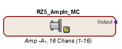
The RZ5_AmpIn_MC macro provides a solution for multi-channel amplifier input via the RZ5, automatically selecting the correct components, applying the appropriate scale factor and channel offsets needed based on information the user provides about the input source. The macro outputs a multi-channel data stream to facilitate multi-channel signal processing and storage.
Amplifier inputs and onboard A/D can also be accessed using appropriate single channel ADCIn components. Single channel data can be converted to a multi-channel data stream using techniques discussed under Combining Channels.
When the input macro is not used see the RZ5 technical reference in the System 3 Manual for detailed information about the RZ5 I/O hardware for scale factors and channel numbers.
The RZ5D Processor
The RZ5D is equipped with a fiber optic port for a direct connection to a PZ Preamplifier and onboard A/D for input of signals from a variety of other analog sources.
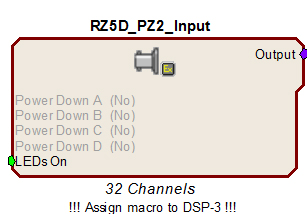
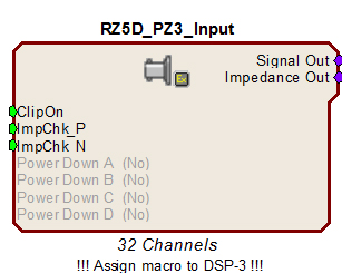
The RZ5D_PZ2_Input and RZ5D_PZ3_Input macros provide a solution for multi-channel amplifier input, automatically selecting the correct components, applying the appropriate scale factor and channel offsets needed based on information the user provides about the input source. These macros output a multi-channel data stream to facilitate multi-channel signal processing and storage. They must be assigned to DSP-3.
Amplifier inputs and onboard A/D can also be accessed using appropriate single channel ADCIn components. Single channel data can be converted to a multi-channel data stream using techniques discussed under Combining Channels.
When the input macro is not used see the RZ5D technical reference in the System 3 Manual for detailed information about the RZ5D I/O hardware for scale factors and channel numbers.
The RZ6 Processor
The RZ6 is equipped with onboard A/D for superior high frequency acquisition. An optional fiber optic port can be equipped for a direct connection to a four channel Medusa Preamplifier.
Important
The RZ6 device macros are required for accessing analog and digital inputs and outputs.
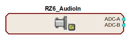
Analog input is accessed in RPvdsEx through the RZ6_AudioIn macro.
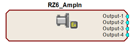
The RZ6_AmpIn macro automatically applies the necessary scale factors and channel offsets for configuring the optional preamplifier fiber optic port.
Note
All RZ6 device macros input or output single channel signals, however, the RZ6 supports multi-channel circuit components. See Combining Channels, for more information on converting single channel signals to a multi-channel signal.
RX Processors
The MCAdcIn component is the best choice to feed the circuit with multi-channel signals when using RX processors. Signals are typically digitized on a preamplifier and then transferred to the base station via fiber optics. This basic acquisition circuit uses the MCAdcIn and a multi-channel filter macro to acquire and filter multi-channel data.
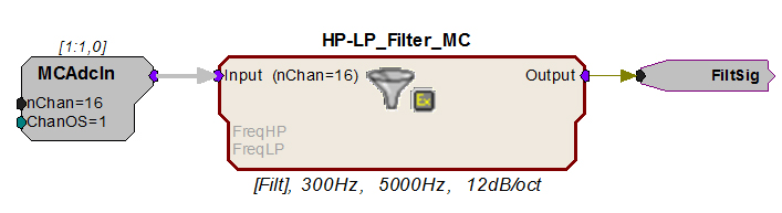
In this sub-circuit, signals on channels 1 - 16 are acquired and filtered. The FiltSig HopOut routes the filtered signals to another area of the circuit for further processing or storage. A similar circuit using single channel components would require 112 components to accomplish this same processing task.
When using the MCAdcIn the user must specify the channels to acquire using the number of channels (nChan) and the channel offset (ChanOS) parameters. For example, the circuit above acquires 16 channels. Because the offset is set to 1, acquisition will begin with channel 1. The user must again consider their hardware configuration. On the RX5, channels 1-16 are acquired via fiber optic port 1. This means that a 16-channel preamplifier must be connected to the Amp-A fiber optic port to acquire all 16 channels of data. A preamplifier connected to the Amp-B port (Channels 17-32) would be ignored.
To acquire 32 channels from two 16-channel amplifiers that are connected to ports A and B, simply change each of the nChan parameters to 32. A single MCAdcIn can be used to acquire any block of consecutive channel numbers. However, if there is a break in the channel numbers to be acquired, multiple MCAdcIns must be used. A MCMerge component is used to combine multiple multi-channel signals into one multi-channel signal.
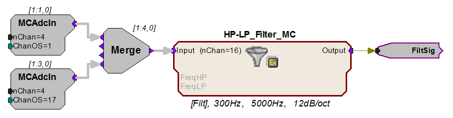
In this example, two MCAdcIns are used to acquire channels 1-4 and 17- 20. This circuit acquires eight channels of data using two 4 channel amplifiers, connected to ports A and B.
The output from MCAdcIn is in floating-point format. The nChan parameter of the filter macro must match the number of channels in the signal input. In the first example, 16 channels are fed directly from the MCAdcIn to the macro. In the second example, a MCMerge component is used to combine the multi-channel signals from two MCAdcIns and a total of eight channels are fed to the macro.
The filtered signals can be processed further or stored to a memory buffer using MCSerStore or a multi-channel data store macro. The signal can also be split into its single channel signals (see "Extracting Channels" below) and processed individually.
Processing and Converting Signals
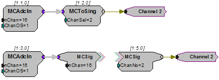
The scope of the multi-channel components is limited to the most common processing tasks. When an acquisition circuit requires additional processing, it will often be necessary to extract single channel signals using the MCToSing or MCzHopPick components.
Extracting Channels and Using Iterations
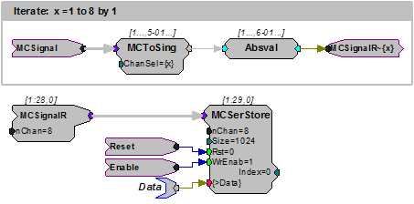
When single channel processing must be performed on many channels, using iterations keeps the circuit manageable. The iteration box is drawn around a sub-circuit that must be repeated a specified number of times. The following example extracts the individual channels from an 8-channel signal called MCSignal using a HopIn and full wave rectifies them. All this is done within an iterate box. The single channels are then recombined using MCFromHop to form an 8-channel signal. The MCFromHop component is only supported by RX and RZ multi-processor devices. For single processor devices such as the RA16BA see Iterate.
The iterate box is used to duplicate the sub-circuit 8 times, extracting 8 single channels from the multi-channel signal. The iterate variable {x} (which corresponds to the iteration number) is used to set the channel number for the HopIn component in each iteration ensuring that each iteration extracts a different channel.
The parameter tag also uses the iterate variable {x} to ensure that each iterated circuit processes a unique channel with a unique set of parameters. The iterative notation MCSignalR~{x} allows the MCFromHop component to reconstruct the multi-channel signal MCSignalR from the 8 single channels. Once reconstructed, the multi-channel signal MCSignalR is then stored using MCSerStore.
Combining Channels
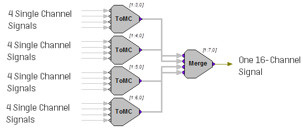
There are two components that combine multiple signal paths into a single multi-channel signal, MCFromSing (ToMC) and MCMerge. MCFromSing (ToMC) is used to build a multi-channel signal from several single channels.

The MCMerge component merges multi-channel signals into higher order multi-channel signals. Each of these components combines up to four signal paths. They can also be used together in sequence to build a larger multi-channel signal.
Data Storage
There are three possible methods for data storage.
OpenEx users can select from a variety of data storage macros designed specifically for use in OpenEx. These macros greatly simplify circuit design for multi-channel data storage.
For users who develop their own applications using ActiveX, RPvdsEx currently supports a limited number of multi-channel buffer operation components.
When no other method is available, use iterate boxes with single-channel buffer operations (similar to the process described above). See the Iterate, for an example of this method.
The example circuits below each pull together acquisition, filtering and data storage in an efficient processing chain.
OpenEx Example
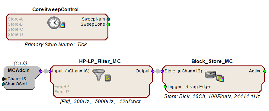
Using OpenEx allows for extensive use of macros for circuit design: from timing to storage. The circuit below uses the Block_Store_MC macro to store a 16 channel filtered input to the OpenEx DataTank using the Store name "Blck".
ActiveX Example
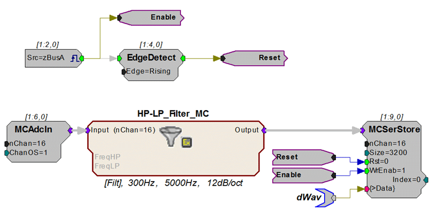
Below, the MCAdcIn feeds the circuit with a 16-channel input. The MCSerStore component stores all 16 channels into a single 3200-point buffer. The dWav parameter tag is used to read the buffer back to the PC.