The Components
Component Overview
Components are the building blocks of the processing chain and perform fundamental processing tasks such as generating a tone, filtering a signal, or summing several signals. RPvdsEx has hundreds of processing components to tailor circuit designs for particular applications.
The following simple processing chain illustrates icons for some typical RPvdsEx components.
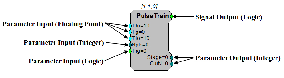
Component properties depend on their function. Components have at most one primary signal input and one primary signal output. In addition, components can have one or more secondary inputs and outputs, also called parameters. Illustrated below is an example of the different color-coding standards seen in RPvdsEx. Floating Point parameters are designated by a teal coloring while Integer parameters are designated by a dark green color. Left side parameters are Inputs, while right side parameters are Outputs.
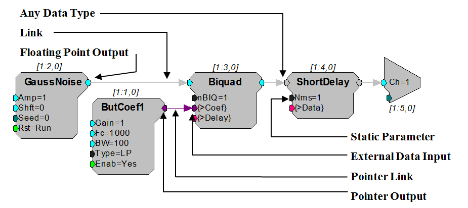
 Component parameters are specified with initial values when the chain is loaded. The user sets these values by clicking on the component symbol and editing the values before the chain is run. Most parameter values can also be changed dynamically while the chain is running. The parameter can be fed from the output signal of another sub-chain or the value can be changed manually from the host PC (via parameter tags). Parameters flagged as static or constant CANNOT be updated dynamically and must be left unchanged while the circuit is running. Static parameters have a black colored input symbol.
Component signal inputs and dynamic parameters usually expect a certain data type such as integer, floating point, or logic. In the example below, the GaussNoise component has an output that generates floating-point numbers. The output from GaussNoise is connected by a link to the floating-point input on Biquad. It is important to match data types when connecting outputs and inputs. Some components, like ShortDelay accept any data type.
Component links may also indicate single (designated by a thin line) or multi-channel (designated by a thicker line) data streams.
When a circuit is compiled, RPvdsEx automatically generates a processing chain that orders components as they will be run. The maximum number of components that can be compiled in a single circuit is 128 for single-processor devices (such as the RA16BA) 256 per DSP RX processor devices (such as the RX5), and 768 per DSP for Z-series processor devices (such as the RZ2).
RPvdsEx has a growing library of processing components. Detailed information, including each component's function and its associated parameters, is described in Component Reference.
Component Numbering
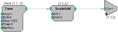
There is a series of numbers listed above each component to denote the DSP number, component number and time slice. The DSPs are numbered with the main processor being assigned number 1. When a circuit is compiled, RPvdsEx orders the components. The component numbers indicate the order components are executed in the processing chain on that particular DSP. The Time Slice number is used to indicate the "time slice" in which a component is executed. For more information, see Time Slices.
In the following figure, the components represent the first two components in time slice zero on the main processor of a multi-processor device or the first two components in a circuit on a classic processor.
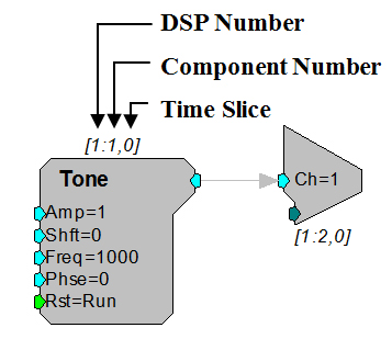
The DSP number and component number ensure that each component on each processor will be assigned a unique set of numbers. For example, components assigned to the main processor will have numbers from (1:1) to (1:256). Components assigned to the first auxiliary processor will have numbers from (2:1) to (2:256) etc.
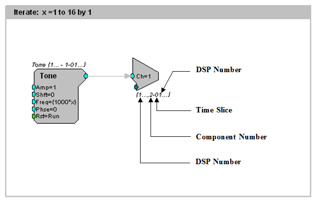
When a circuit segment is replicated across several processors or duplicated with an iterate box, the numbering scheme changes to reflect this difference. See Duplication Information.
Links Treated as Components
Links pass signals or parameter information between components. Some links are only a graphical representation of signal flow and do not correspond to any additional processing task; for example, passing a signal from one process (component) to the next process (component) in sequence. Other links, however, do represent processing tasks, such as routing a signal to a second process that occurs later in the processing chain. Because these links contribute to the overall demand placed on the processor, they are treated as components and given a component number. To keep the circuit diagram from becoming cluttered and confusing, the component numbers assigned to links are hidden, but it is important to keep in mind the contribution they make to the total number of components in a circuit.
The four types of link components are listed below.
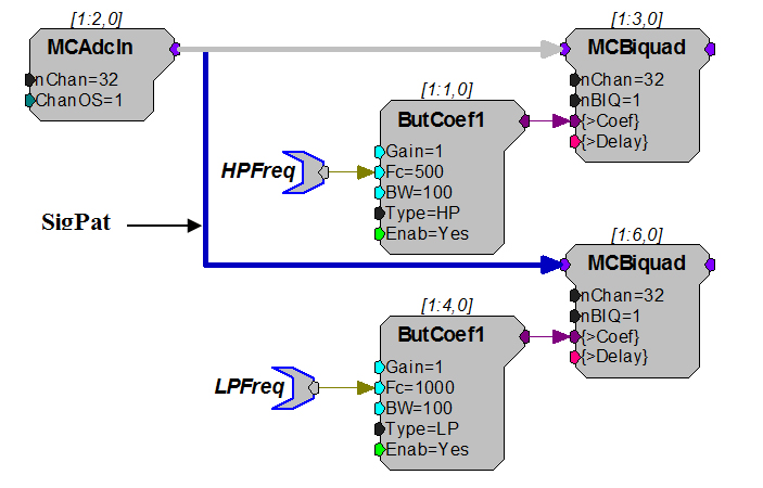
SigPatch: A SigPatch is created when a component's primary output signal is routed to two or more primary inputs. Because the signal must be delayed and routed to a later process (component) any link to a primary input beyond the initial connection is treated as a SigPatch component.
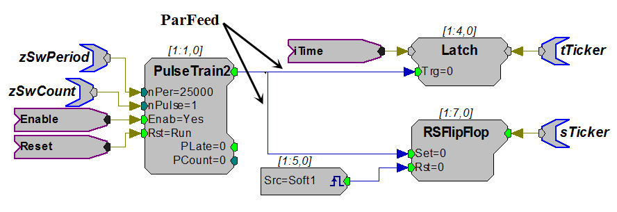
ParFeed: A ParFeed is created when the primary output signal is routed to a parameter input.
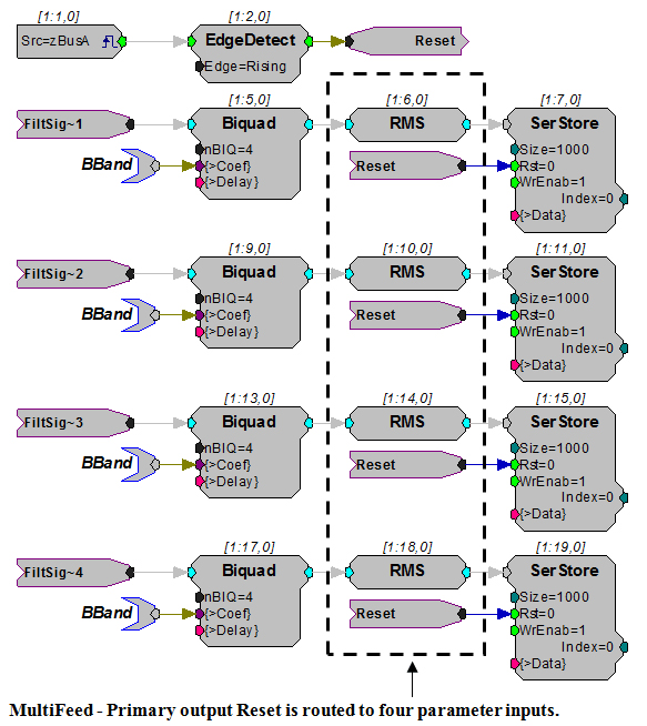
MultiFeed: A MultiFeed occurs when a primary output signal is routed to four or more parameter inputs. This is an extension of the ParFeed component.
A single primary output routed to three parameter inputs is treated as three ParFeed components. A single primary output routed to four or more parameter inputs is treated as one MultiFeed component.
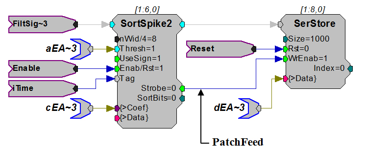
PatchFeed: A PatchFeed is when a parameter output signal is routed to a parameter input.
Data Types
When working in RPvdsEx, data types for component inputs and outputs are color coded and type checking is performed automatically. Component ports of like colors can be linked together. Illegal links are flagged as errors and colored red when the circuit is compiled.
The following table lists currently supported data types and their general use:


Parameter Access Rules
Every component has a number of inputs and outputs called parameters. The parameters of a component control how the component functions when running in the processing chain. For example, the Freq parameter of the Tone component controls what frequency signal will be generated by the Tone component.
Dynamic Access
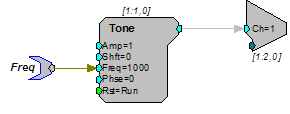
Most processing components support some number of parameter ports that have an initial value and are later changed 'dynamically' while the chain is running. An example of this is shown below where the frequency of the Tone is initially set to 1000 Hz. This value can then be changed dynamically using ActiveX controls and the parameter tag called Freq.
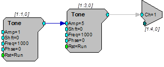
Another method of dynamically changing a component parameter is to 'feed' the parameter with the output of another component. The example below shows how to create an AM signal by feeding the output of one tone generator into the Amp parameter input of another.
Here the initial value of 5, specified in the second Tone's Amp parameter, has no effect because this value is over-written on the first tick of the sample clock with the output of the modulator Tone component.
Static Access
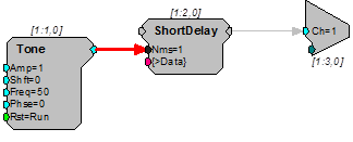
Some parameter inputs cannot be changed while the chain is running. They are called static or constant. When working in RPvdsEx static parameters are color coded in black and connecting to them, as shown below, will generate an error (link shown in red).
Data Port Access
All Buffers and components that buffer signals, such as filters, have a data port. This port allows direct access to the dynamic memory and program memory of a component. This allows users to load data from a program, file, or helper component to a memory buffer on a component such as a Serial Buffer or data can be downloaded to the computer from the memory buffer. The data port (that is, the dynamic memory of the component) is accessed through helper components from within RPvdsEx or using ActiveX controls.
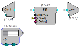
The DataTable and SourceFile can be used to send data to a data port. For example, to use a specialized digital filter such as an IIR or FIR a data table is created that contains the coefficients for generating the filter. In the example below a DataTable component sends coefficients to the filter. A data table can have hundreds of filter coefficients. Before the circuit is run the filter properties can be changed within RPvdsEx by clicking the up and down arrows on the DataTable component.
Time Slices
By default, components are calculated on every tick of the processor's sample clock. However, there are situations where it is not necessary to calculate a component on every sample and it wastes processing cycles to do so. Time slices provide a means of processing some components less frequently. Most components are assigned a time slice of 0, meaning that they are processed in all time slices (on every tick of the processor's sample clock). However, some components are assigned to a specific time slice (n) and are only processed on the nth time slice of a user defined number of time slices.
For example, if you are generating filter coefficients for a low-pass filter and the frequency of the filter does not change, you don't need to calculate the filter coefficients on every sample of the clock (in fact you may only need to calculate them once). So, to conserve cycle usage on the DSP, you could set the coefficient generator to generate coefficients in a particular time slice, say time slice 1. If there are 10 time slices total, then the coefficients will be calculated once every 10 samples. The total number of time slices and the time slice value for individual components can be set from within RPvdsEx.
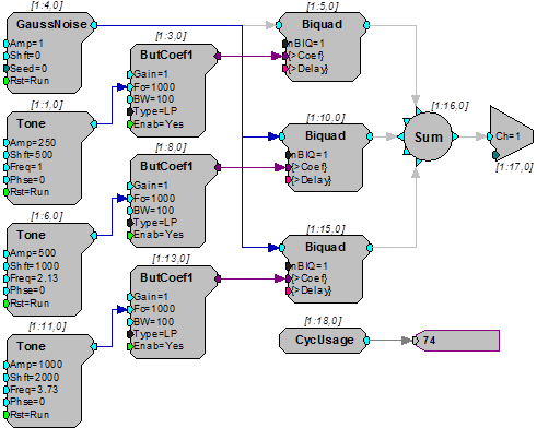
Consider the following example where three bands of noise are FM modulated to create a single output. The rates of modulation are low so the coefficient generator components can be run at a decimated rate but all components, including the coefficient generators are processed on every tick of the sample clock.
The following diagram shows the circuit without time-slicing, notice the cycle usage is over 70%.
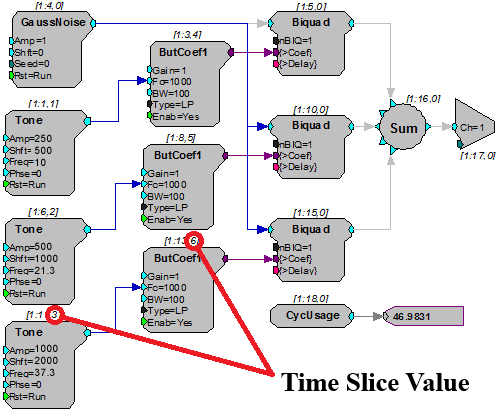
To improve circuit performance and 'free-up' DSP power for doing some other processing, we can move all three modulating Tone generators and their corresponding ButCoef1 coefficient generators to time-slices. Each will be placed in its own time slice reducing the DSP cycle usage to about 45%. Note that because the Tone components are now running at 1/10th the actual sample rate their frequencies must be multiplied up by a factor of ten. The resulting diagram is shown below with a chart showing sample-by-sample cycle usage for each time-slice.
Same circuit with time slicing used, note cycle usage has been reduced to 47%.
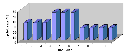
The chart below illustrates cycle usage for each of the ten time-slices.
Note
Time slices 7 through 10 have the lowest current usage and should be used next when a time slice is needed.
Setting the Number of Time Slices
The number of time slices is set in the Set Hardware Parameters dialog box. To open the dialog, click the Device Setup command on the Implement menu. The maximum number of time slices is 200.
Specifying a Time Slice
To specify the time slice in which a component will run, double-click the component and enter the desired number in the Time Slice box in the component's dialog box.
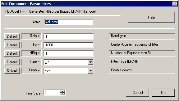
Duplication Information
When a circuit segment is replicated across several processors or duplicated with an iterate box, a Duplication Information dialog is available to display the item number, name, component number, time slice and parameters for each of the duplicated components.
By right-clicking the replicated component, the user can view a table like the following:
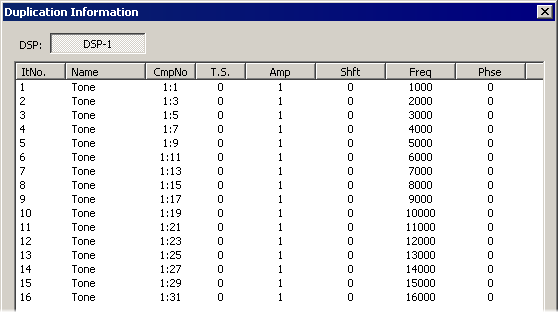
This table was generated for a Tone component duplicated 16 times in an iterate box with the Freq parameter incremented with the iteration number. If this component were also replicated across multiple processors, there would be tabs for each applicable processor next to the DSP-1 tab. The duplication information can also be accessed when editing the component's parameters by clicking on the Duplication Info button.
Also when a component is replicated or duplicated, the component numbering scheme changes. The following figure shows the numbering to reflect the duplication:
The second DSP number is used to display the range of applicable DSPs if the circuit segment is replicated across multiple processors. For example, if the circuit segment were assigned to the main processor and replicated on two auxiliary processors, the second DSP number would be 3.