Digital I/O Circuit Design
Digital I/O is extremely useful for producing logical status or control signals. Many System 3 devices allow digital I/O to be configured through RPvdsEx. To determine which bytes are available, see the reference section for your device in the System 3 Manual .
Working with BitIn - BitOut
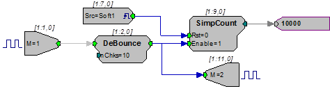
This simple logic circuit using BitIn and BitOut will increment a simple counter for every sample that bit-0 is a logic high. A DeBounce is used to filter transients from a switch, such as a button press. A software trigger can be used to reset the counter to 0. Bit-1 will output a logic high whenever the counter is enabled and incrementing. This logic high can be output as a control bit or as a status bit such as an LED. The input logic on the RP2 device is set for logic high (5 Volts in). For a circuit to work when a button press occurs, invert the output using a NOT gate component.
Note
Bitmasks always start with bit-0. Use 2n and insert the bit needed to use the correct mask value. For example, to use bit-3, compute 23 or a mask value of 8.
Working with WordIn - WordOut
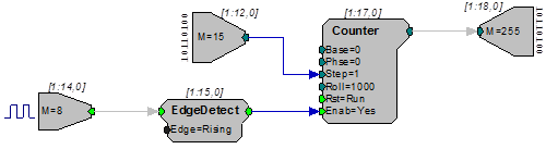
This circuit demonstrates the use of WordIn and WordOut and how the mask parameter is used to assign bits of the input and output ports to different tasks. In this example, bit-8 of the input port is used to trigger the counter shown. On each rising edge of bit-8 the counter will be advanced by the value input on bits 0 through 3 of the input port. The resulting count output is fed to all eight bits of the digital output port. The EdgeDetect component makes sure that only one value is saved for each logic high present at its input.
Addressing Digital Bits In A Word
Some high performance processors include digital I/O that must be addressed as a word. Word addressable bits can be addressed using the WordOut RPvdsEx component. To address these bits you must first specify the maximum bitmask value in the WordOut component for the byte that contains the bits you want to address. The table below includes a list of the maximum values for each byte. These values apply to any module with a digital I/O word.
Table 1
Note
Not all devices include all four bytes. To determine which bytes are available, see the reference section for your device in the System 3 Manual .
Addressing Separate Bits in a Byte
It is possible to address each bit in a byte separately depending on the integer value sent into or out of the WordIn or WordOut component. The following table shows the integer values for each bit in each byte.
Table 2
For example:
When addressing Byte C, the bitmask value on the WordOut component should be 16,711,680. Then, to address bit 5 an integer of 2,097,152 should be sent into the WordOut. Both of these values are required to send a pulse out to only Bit 5 in Byte C. The following table shows the alignment of the bits to complete the operation.
Note
This will also light up the Bit 5 LED on the device if the device's Bits Lights are configured to Byte C. For more information on configuring Bits Lights, see the "Digital Input/Output" section for your device in the System 3 Manual .
Addressing More Than One Bit in a Byte
The values in the table above will only address one bit at a time. However, it is also possible to address a combination of bits. For this task, determine what bits you would like to address in a specific Byte and then convert that binary value to decimal. However, before converting this value to decimal, consider the location of each byte in the digital word. Byte A is converted as normal, but Byte B is shifted left by 8 bits (add eight 0s to the end of the binary value), Byte C sixteen 0s, and Byte D twenty-four 0s. The decimal value is the integer to send into the WordOut component (or the integer coming in from a WordIn component).
For example:
To address all of the bits in Byte B, set the Bitmask value in the WordIn or WordOut component for Byte B (see Table 1) and then determine the integer value to be sent into the component (calculated in steps below).
Since we are attempting to address all eight bits of a byte, the binary value should be eight 1s:
1111 1111
For Byte B, eight 0s should be added to the binary value making the value:
1111 1111 0000 0000
The binary number converted to decimal is:
65,280
Therefore, an integer of 65,280 should be sent to a WordOut component with a BitMask value of 65280 (this value from Table 1). Another way to complete the same operation is to add the integer values of the bits you want to address in a given byte (Table 2) to determine the integer value to send to the WordOut component.
Addressing More Than One Bit in a Byte using the RPvdsEx iBitShift Component
When addressing bits in a digital word, the integer value out can range from 1 to 2,147,483,648. Since each group is addressable as a single byte, it is often easier to assign values in a range from 1 - 255 then use an iBitShift to move the integer by a fixed number of bits to the left or right. When addressing different bytes, you need only modify the iBitShift "N" parameter.
For example:
Byte A would use a bit shift of 0, while Byte B would require a bit shift of 8 for output and -8 for input. Circuits that use Byte C would use 16 and -16 and D would use 24 or -24. Designing circuits using this method makes it possible to read in the bit values for Byte D using integers from 1 - 255 as compared to integers between 16,777,216 and 2,147,483,648. Using iBitShift also allows values to be processed using ToBits or FromBits.
The following example circuit shows how the iBitShift component can be used with Word components to remove the eight least significant bits in a 16-bit integer.
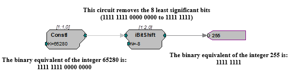
As the example (above) explains, the iBitShift is used to remove the eight least significant bits from the integer 65280. The integer 65280 corresponds to eight high bits in Byte B. The next example (below) shows an iBitShift that removes the eight least significant bits from a WordIn component that is bitmasked to Byte B. The ToBits component then separates the bits and each bit is sent out to the first six addressable bits.
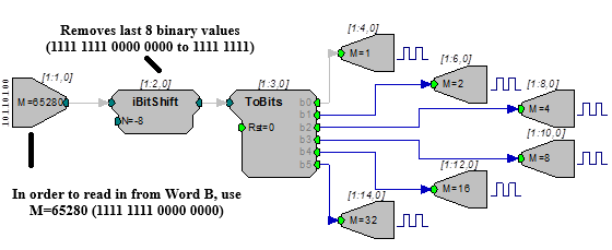
The ToBits component is only used for up to 6 bits; it may give errors if the 7th or 8th bits are used.
Note
The first 6 addressable bits must be configured as outputs and Word B must be left as an input.