The RPvdsEx Environment
Overview of the Workspace
The RPvdsEx workspace has been designed for ease of use and flexibility. Circuit diagrams, representing the processing chain, are created on the sheets of a tabbed window using drag-and-drop techniques. Unless otherwise assigned, all sheets of a window form a single complete circuit. When using a multi-DSP device, sheets or segments of the circuit can be assigned to one or more processors.
Windows and toolbars can be arranged to customize the workspace for easy access to commonly used components and design tools. Before making changes to the workspace it will appear similar to the illustration below.
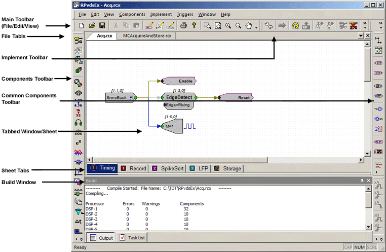
The workspace contains the following elements:
Main Toolbar (File/Edit/View)
Open, create, and save files or zoom and pan the view.
Implement Toolbar
Access tools for compiling and running the circuit or select and configure the device setup.
Components Toolbar
Select a group button to access hundreds of components for signal processing tasks; organized into intuitive groups.
Common Components Toolbar
Select one of the most commonly used components.
Tabbed Window
Displays the current sheet. Click and drag to arrange and connect components to form a circuit diagram.
Sheet Tabs
Sheets are navigated using tabs at the bottom left corner of the tabbed sheet window allowing you to quickly switch between areas of the circuit. Sheets organize complex circuits and allow you to assign individual sheets to one or more DSPs on a multi-DSP device. They can be added and removed at any time.
Build Window
View compilation status, errors, or warnings or select an error in the list to navigate to the problem area of the circuit.
Menus and Toolbars
RPvdsEx provides you with a full set of menus and toolbars. Using menu commands and toolbar buttons, you can create, open, and save circuit files; build new circuits or edit existing circuits; and access hardware configuration settings. The menus and toolbars are covered in detail in the Menu and Toolbar Reference.
The Sheets
When a new file is created a default sheet, Sheet 0, is created and displayed in the tabbed window. Sheets can be added, removed, resized, or renamed using a shortcut menu accessed by right-clicking the tabbed window.

When using a multi-DSP device, users can assign each sheet to one or more processors or a core. Users can move around the sheet and adjust the zoom level using commands found on the View menu.
Viewing Sheets
A circuit diagram may be contained on a single sheet or across multiple sheets. By default, magnification is set to allow the components to be viewed clearly. Areas out of view can be brought into view using standard MS Windows scroll bars or zoom and pan features. A sheet can be brought to the foreground by clicking the corresponding tab located in the bottom left corner of the window.
Zoom and Pan Features
Zoom and pan features are available on the View menu or on the main toolbar.
 Zoom: When the Zoom command is selected, the pointer changes to a magnifying glass and clicking an area of the sheet zooms in on that area. The Zoom command is in effect until another zoom or pan feature is selected.
Tip: To quickly turn off the Zoom command, select the Pan feature and click the sheet once.
 Zoom To Fit: When the Zoom To Fit command is selected magnification is automatically adjusted so everything on the current sheet is in view.
 Zoom In: When the Zoom In command is selected magnification is increased. The command can be selected again to further increase magnification.
 Zoom Out: When the Zoom Out command is selected magnification is decreased. The command can be selected again to further decrease magnification.
 Pan: When the Pan command is selected the pointer changes to a hand and dragging moves the sheet in the corresponding direction. The pointer returns to normal after one use. The Pan command can be selected again to move the sheet again.
Adding and Removing Sheets
A single circuit diagram can be divided across several sheets to make working with the circuit more manageable.
To add a sheet:
Right-click the window and click Add Sheet on the shortcut menu.
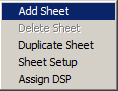
The sheet is added to the window and a tab for the new sheet is visible in the bottom left corner.
To remove a sheet:
Click the tab for the sheet to be removed.
Right-click the window and click Delete Sheet on the shortcut menu.
Warning
Any portion of the circuit diagram on the current sheet will be lost when the sheet is deleted.
Click Yes to confirm the deletion.
To move a sheet:
- Click and drag the tab of the sheet you wish to move.
Renaming a Sheet
Sheet names can be used to add organization to circuits, making it easier to move directly to an area of interest.
To change the sheet name:
-
Right-click the window and click Sheet Setup on the shortcut menu.
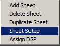
-
Type a new name in the Sheet Name box.
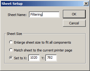
-
Click OK.
Changing the Sheet Size
The default sheet is 1020 x 782 pixels. If a component is dragged off of the sheet, RPvdsEx will automatically resize the sheet to include the component. The size of the current sheet can also be modified in the Sheet Setup dialog box. The default sheet size for all new files can be changed in the Preferences dialog, available from the Edit menu.
To change the sheet size:
-
Right-click the window and click Sheet Setup on the shortcut menu.
-
Select one of the Sheet Size options.
To use the Set to X:___ Y:___ pixels option, type new values in the X and Y boxes.
See Choosing a Sheet Size Option below for more information on the available options.
-
Click OK.
The change is applied to the current sheet. Other sheets in the file are not changed.
Choosing a Sheet Size Option
The Sheet Size options provide users with an extra measure of flexibility. They also provide quick solutions for the common situations listed below.
Duplicating Sheets
When parallel structures must be added to a circuit, such as additional channels of filtering or acquisition, it might save time to duplicate an existing sheet.
Be sure to review the new sheet and make any necessary modifications after duplication.
To duplicate a sheet:
Click the tab corresponding to the sheet to be duplicated.
Right-click the window and click Duplicate Sheet on the shortcut menu.
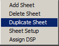
Review the duplicate sheet and re-index items such as parameter tags with channel numbers and update the parameters of components as needed.
Assigning Sheets to a DSP
When a multi-DSP device is used, the user can assign each sheet of an RPvdsEx file to one or more processors and a particular core of a quad core processor. Multiple sheets can be assigned to the same processor. Because the architecture of RX and RZ multi-processor devices differs, they are handled slightly differently.

Regardless of the processor type, an icon on the sheet tab indicates which processor has been assigned, and if multiple processors have been assigned. See Sheet Icons, for more information. If a processor is a QDSP (quad core) processor and QDSP has been enabled in the Set Hardware Parameters dialog, a core letter is also displayed. See Manual Device Selection, for more on using the Set Hardware Parameters dialog.
RZ Devices
By default all sheets are assigned to the first processor, DSP-1 and if the DSP is a quad core DSP, the sheet is assigned to Core-A.
To assign a sheet to a processor(s):
-
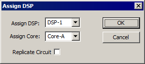
Right-click the sheet and click Assign DSP . The Assign to DSP dialog box is displayed.
-
Select a DSP from the drop down list and, if needed, select a core. If you wish to replicate the circuit on multiple DSPs, click the Replicate Circuit check box to display an extended view. Click and clear check boxes to select or deselect the processor(s) to be assigned to the sheet.
Note
Users should be familiar with the number of DSPs available in their device and only assign sheets to those DSPs.
-
Click OK.
RX Devices
By default all sheets are assigned to the main processor.
To assign a sheet to a processor:
Right-click the sheet and click Assign DSP . The Assign to DSP dialog box is displayed.
Click OK .
To replicate the circuit on a sheet on multiple processors:
Right-click the sheet and click Assign DSP . The Assign to DSP dialog box is displayed.
Click the Replicate Circuit check box and select the check boxes for the desired processor(s).
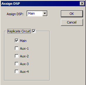
Click OK .
Single Processor Devices
All sheets are assigned to a single processor and the Assign DSP functionality is not available.
Sheet Icons

When sheets in an RPvdsEx file are assigned to different processors in a multi-processor device such as an RZ2, an icon next to the sheet name identifies the associated processor as illustrated in the figure above. The icons are described as follows.
RZ Devices
 A processor (1 through 8) as designated by the numeral in the icon.
 A QDSP Processor (1 through 8) as designated by the numeral in the icon and a core (A - D) as designated by the letter on the icon.
 Replicated sheet - a sheet that is assigned to more than one DSP.
 Replicated QDSP sheet - a sheet that is assigned to more than one QDSP processor - lowest number processor is designated by numeral and a core (A - D) as designated by the letter on the icon.
RX Devices
 Main processor.
Auxiliary processors 1 through 4 as designated by the Roman numeral in the icon.
 Replicated sheet - a sheet that is assigned to the main processor and replicated on one or more of the auxiliary processors.
The Build Window
The Build Window (previously called the message window) is provided specifically for compilation and error reports. By default, the window is docked at the bottom of the RPvdsEx workspace. The window can be moved and resized and has two tabs - Output and Task List.
Output
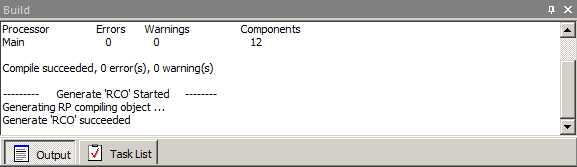
The Output window displays details about the compilation such as the start and success of compiling, loading, and running the current circuit. It also displays errors and warnings encountered while compiling. If more than five errors are encountered on compilation, compiling stops, and a Build failed error is displayed.
If a multi-processor device is specified in the hardware setup, this window also reports the number of components on each processor when the circuit compiles successfully.
Task List
The Task List window displays details about the errors and warnings listed on the Output tab. It consists of four columns - Type, Sheet, Symbol, and Error.
Type tells the user whether the item is an error or warning.
Sheet specifies the sheet name or number where the error or warning can be found.
Symbol specifies the specific component, hop, or symbol that caused the error.
Error describes the problem through a comment.
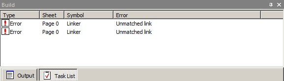
Errors listed in the Task List are highlighted in the circuit diagram in red and warnings are highlighted in blue. To quickly access the sheet on which the error or warning occurred, click the icon next to the message. The correct sheet will be displayed and the error or warning will appear in bold black in the circuit diagram. Click the icon again to toggle the colors between bold black and red for errors and blue for warnings. To troubleshoot RPvdsEx related problems, see Common RPvdsEx Error Messages and Warnings.
Compiling Selected Processors
When using an RX multi-processor device it is possible to compile, build, and run segments of the circuit assigned to a selected individual processor. This gives the user more control over the compilation process. By default, when a circuit is compiled, the entire circuit is compiled. After a single processor select command (such as Main DSP or Aux One) has been selected, all compilation and code-building tasks are performed on the selected processor only. For example, if Aux One has been selected and the compile button is clicked, only segments of the circuit assigned to auxiliary processor one will be compiled and the messages window will display the result of compilation and number of components for auxiliary processor one only.
Accessing the Processor Selection Commands
The processor selection commands are available from the Implement menu or the Processor Select toolbar.
 Main DSP Selects main processor
 Aux One Selects first auxiliary processor
 Aux Two Selects second auxiliary processor
 Aux Three Selects third auxiliary processor
 Aux Four Selects fourth auxiliary processor
 All DSPs Selects all processors
When a processor is selected, its icon (menu) or button (toolbar) will appear "pressed." Either a single processor or all processors may be selected. Selection of two, three, or four processors is not supported.
Note:
These commands are only available when the device selected in the Set Hardware Parameters dialog box is an RX device.
Hop Related Compilation Errors
Circuits that use zHops or MCzHops might generate errors when compiling only a single processor of a multi-processor circuit. The zHops and MCzHops allow transfer of signals between processors within a device and must be used in pairs.
If the matching zHops are assigned to a processor that is not being compiled, a "No matching zHop found" error will be generated for each zHop used. If the circuit uses zHops it must be modified before it can be compiled. For more information about zHops see MCzHopIn and zHopIn.
File Formats
The circuit designed in RPvdsEx is loaded to the processor as a control object. The control object contains the compiled processing chain (DSP code) for the circuit diagram and can be used with TDT run-time applications or custom programs developed using TDT ActiveX controls.
By default, both the graphical circuit representation and the compiled control object are saved in a single file with the .rcx format. RPvdsEx also supports the legacy two-file format used by earlier versions of TDT software.
Legacy File Formats
The legacy format consists of two separate files. The circuit diagram is saved in one file in an .rpx or .rpd format and the control object must be saved separately in an .rco format.
To revert to the legacy RPX/RCO file system:
On the Edit menu, click Preferences .
Clear the Embed RCO object file check box.
Click OK .
After performing this step, the Build RCO command is enabled (available on the Implement menu or on the Implement toolbar) and can be used to save the control object as a file with the .rco extension.
Device Setup
Some RPvdsEx features and components are not supported by all device types. To ensure all the features available for your device are enabled, ensure the correct device type is selected before beginning circuit design.
Automatic Device Detection
If a TDT system is connected to the PC running RPvdsEx and a new circuit is created, RPvdsEx will automatically set the device type to the processor module highest on the Device List in the connected system.
Manual Device Selection
The automatically selected device type can be overridden using the hardware setup parameters.
To set the device type:
Click the Implement menu or click the  button.
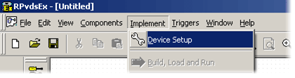
Click Device Setup to open the Set Hardware Parameters dialog box.
In the Device Select group box, select your processor from the Type drop-down menu.
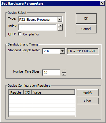
Depending on the device selected, the dialog box may expand to allow configuration of more options, such as arbitrary sampling rates or digital I/O configuration.
If your processor contains qDSP cards, click the QDSP compile for check box to enable QDSP features.
Click OK .
Hardware Parameters
In addition to device selection, the Set Hardware Parameters dialog can be used to set related parameters, such as device index and sampling rate.
Index
Devices in a TDT system are indexed according to their logical order, that is, the order of the connections between devices. Each device type is indexed beginning with 1. So, index numbers higher than one only occur when the system includes more than one module or device of the same type. The index number for a particular device can be verified using TDT's zBusMon program.
Sample Rate
In the Bandwidth and Timing area, you can select from a list of Standard Sample Rates. Sample rates in the drop down menu are approximations. The actual sample rate is shown to the right. If the selected device supports arbitrary rates, the Set Hardware Parameters box expands to include an option for input of arbitrary rates.
Time Slices
In general, the entire processing chain is executed on each tick of the sample clock. Time slices provide a means of processing some components less frequently. When time slices are defined, by specifying the number of time slices here, you can assign some components to a specific time slice (n), and they are only processed on the nth time slice of the defined number of time slices. For more on using time slices, see Time Slices.
Device Configuration Register
Many devices include hardware components, such as programmable digital I/O that can be configured using the Device Configuration Register. If the selected device includes configurable features, the dialog box will expand to display the Device Configuration Register. See the reference for your device for configuration information.