Basic Math
The Basic Math components are used to perform low-level math operations. Remember that even simple math operations might use many DSP cycles. For example, the Divide processor will use about 30 cycles while ScaleAdd uses only about 10 for both a multiplication and addition. Avoid the Divide, SqRoot, and Modulus processors whenever possible.
This group includes the following components:
- AbsVal
- Bound
- Ceiling
- Compare
- Divide
- Floor
- Limit
- Min
- Max
- Modulus
- ScaleAdd
- Sign
- SqRoot
- Square
- StereoScale
- StereoSum
- Sum
- Mult
This group also includes the following components, if RPvdsEx Device Setup is configured for a high performance device, such as the RXn or RZn:
AbsVal
Description:
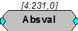
AbsVal computes the absolute value of the signal.
Equation:
Output = Abs (Input)
Example(s):
AbsVal (-2.3) = 2.3
AbsVal (2.3) = 2.3
Bound
Description:
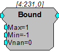
Bound functions similarly to the Limit component but evaluates to Vnan for inputs that produce a NaN (not a number) error.
Note
NaN is output when a division by 0 is applied to a signal value.
Equation:
If Input > Max then Output = Max
Else If Min \<= Input \<= Max then Output = Input
Else If Input \< Min then Output = Min
Else If Input = NaN then Output = Vnan
Ceiling
Description:
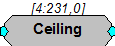
Ceiling rounds the input to the next highest integer value (returned in floating point format). If the input is a negative value, Ceiling rounds towards zero.
Equation:
Output = Ceiling (Input)
Example(s):
Ceiling (2.3) = 3.0
Ceiling (-2.3) = -2.0
Ceiling (-2.7) = -2.0
Compare
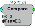
Description:
This component uses a specified test to compare the input signal to a specified value, K. The output reports the result, true or false, as a logical value. The comparison test can be any of the following: equal to, not equal to, greater than, less than, greater than or equal to, or less than or equal to. The Compare component can be thought of as an If... statement. For example, If the signal value equals K then the output is true (1).
Equation:
Output = Compare (Input Test K)
Example(s):
K = 20; Test = EQ
When Input = 20, Output = 1; otherwise Output = 0
K = 20; Test = GT
When Input > 20, Output = 1; otherwise Output = 0
Divide
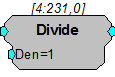
Description:
This component divides the input signal by the denominator and passes the quotient to the output. Division by zero results in an error value. The Divide component can also be used to multiply by defining a Den value between zero and one.
The ScaleAdd and Mult components offer similar functionality and can also be used to divide. The ScaleAdd is the most efficient of these three components and should, therefore, be used whenever possible.
Equation:
Output = Input / Den (Denominator)
Example(s):
PowerBand, PowerBand.
Biquad Filter, Biquad.
Floor
Description:
Floor rounds the input to the next lowest integer value (returned in floating point format). If the input is a negative value Floor rounds away from zero.
Equation:
Output = Floor (Input)
Example(s):
Floor (2.3) = 2.0
Floor (-2.3) = -3.0
Limit
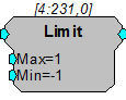
Description:
This component limits the signal to a range defined by the Max and Min parameters. If the input is greater than Max, the signal out is the Max value. If the input is less than Min, the signal out is the Min value. If the input is between the Min and Max values it is passed through as the signal output without change.
Note
If Max is defined as a value less than the defined Min value, the output will always be the defined Min, regardless of the input value.
Equation:
If Input > Max then Output = Max
Else If Min \<= Input \<= Max then Output = Input
Else If Input \< Min then Output = Min
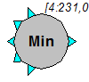
Min
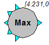
Max
Description:
The Max and Min components evaluate multiple input signals and pass the maximum or minimum input to the output. All input signals must come from the primary output of another component. If it is necessary to route a parameter output to this function use a ConstF to make it a primary output.
Example(s):
Fo = Min (Fi1, Fi2, Fi3, Fi4, Fi5)
Fo = Max (Fi1, Fi2, Fi3, Fi4, Fi5)
Min (4.0, -12.3, 22.7) = -12.3
Max (-3.0, 4, 16.2) = 16.2
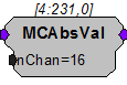
MCAbsVal
Description:
MCAbsVal computes the absolute value of the multi-channel signal.
Note
This component is for use with only high performance processor devices, such as RXn or RZn.
Equation:
FoN = Abs(FiN)
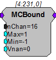
MCBound
Description:
MCBound functions similarly to the Limit component but evaluates to Vnan for inputs that produce a NaN (not a number) error.
Note
NaN is output when a division by 0 is applied to a signal value.
Note
This component is for use with only high performance processor devices, such as RXn or RZn.
Equation:
If FiN > Max then FoN = Max
Else If Min <= FiN <= Max then FoN = FiN
Else If FiN < Min then FoN = Min
Else If FiN = NaN then FoN = Vnan
MCDotProd
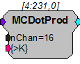
Description:
MCDotProd computes the dot product of the multi-channel input signal and the vector data entered on {>K}. The number of elements for {>K} must match nChan (for example, when nChan is set to 4, {>K} is a 4 x 1 matrix).
Note
This component is for use with only high performance processor devices, such as RXn or RZn.
MCMatMult

Description:
MCMatMult performs matrix multiplication of the multi-channel input signal and the matrix data entered on >K. The dimensions for >K must match nChan (e.g., when nChan is set to 4, >K is a 4 x 4 matrix).
Note
This component is for use with only high performance processor devices, such as RXn or RZn.
Equation:
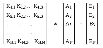
K x A = B
Where, K is the N x N scaling matrix. A is the input N x 1 matrix, one data point for each of the N input channels and B is the output N x 1 matrix, one data point for each of the N output channels. N is the total number of channels (nChan).
The operation is computed on every sample based on the current input provided.
B1 = K1,1 * A1 + K1,2 * A2 + K1,3 * A3 + ... K1,N * AN
.
.
.
BN = KN,1 * A1 + KN,2 * A2 + KN,3 * A3 + ... KN,N * AN
Ordering:
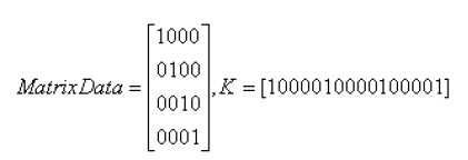
The matrix data for K must be loaded as a vector. Matrix row data is concatenated to form the vector. For example, to load a 4 x 4 identity matrix:
In RPvdsEx, the >K scaling matrix is typically loaded using a DataTable component. Load the K matrix as a column vector using the nRow Type/Format shown below. The No. Rows value is equal to N * N (or in this case 4 * 4 =16).
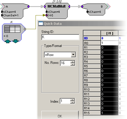
In this diagram, the DataTable K is used to load the identity matrix. The number pattern from above K = [1000 0100 0010 0001] is listed in the first column.
Note
The DataTable component allows a maximum of 1024 rows. This would correspond to a 32 x 32 scaling matrix. This means that the maximum number of channels you can use with this component is 32. If you need to use a larger channel amount, a SourceFile component or parameter tag can be used to load in a larger scaling matrix.
MCScale
Description:
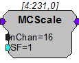
MCScale multiplies each signal in a multi-channel input by the value of the SF parameter. The scaled signals are output as a multi-channel signal. The SF parameter input can be used to update the scale factor dynamically.

Note
This component is for use with only high performance processor devices, such as RXn or RZn.
Equation:
Output[x] = Input[x] * SF
MCSign
Description:
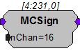
This component determines the sign of the multi-channel input and outputs either -1 (signal with negative value), 0 (signal with no value), or 1 (signal with positive value).
Note
This component is for use with only high performance processor devices, such as RXn or RZn.
Equation:
If FiN < 0.0 then FoN = -1
Else If FiN = 0.0 then FoN = 0
Else If FiN > 0.0 then FoN = 1
MCSum
MCMult
MCDivide
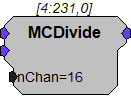
Description:
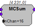
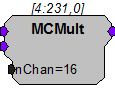
These multi-input components perform basic summation, multiplication, and division of two multi-channel inputs.
Note
This component is for use with only high performance processor devices, such as RXn or RZn.
Equation:
Output =(Input1ChN + Input2ChN)
Output =(Input1ChN * Input2ChN)
Output =(Input1ChN / Input2ChN)
Examples:
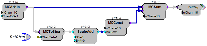
This circuit acquires 16 channels of input, and performs digital subtraction of one channel from all the others. The channel to be subtracted is defined by the parameter tag named RefChan.
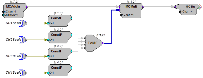
This circuit shows how to scale each channel of an MC input by a different scale factor.
Note
Use the MCScale component when all signals are to be scaled by the same value.
MCSqRoot
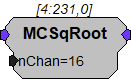
Description:
This component computes the mathematical square root operation across all input channels. The function has a lower bound of 0.
Equation:
FoN = FiN1/2
MCSquare
Description:
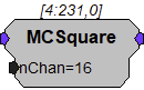
This component computes the mathematical square operation and passes the result to the output.
Equation:
FoN = FiN2
Modulus
Description:
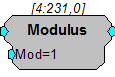
Returns the remainder after the input is divided by the modulus.
Note
Check Known Anomalies for updates on this component.
Equation:
Output=Mod (Input)
For example: Input=5, Mod=2: Output = 1. (i.e. 5/2=2 with remainder of 1)
ScaleAdd
Description:
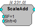
ScaleAdd multiplies a signal by the value of the SF parameter and then sums the result with the Shft value.
Note
the SF and Shft parameters can be set to a constant value or connected to signal sources. This enables the ScaleAdd function to be used to multiply two signals, add two signals, or take the product of two signals and sum it to a third.
Using ScaleAdd to sum two signals is preferable to using the multi-input sum function because it saves DSP cycles.
Equation:
Output = (Input * SF) + Shft
Note that Shft can be another signal.
Sign
Description:
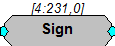
This component determines the sign of the input and outputs either -1 (signal with negative value), 0 (signal with no value), or 1 (signal with positive value).
Equation:
If Fi < 0.0 then Fo = -1
Else If Fi = 0.0 then Fo = 0
Else If Fi > 0.0 then Fo = 1
SqRoot
Description:
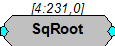
This component computes the mathematical square root operation. The function has a lower bound of 0.
Equation:
Fo = Fi1/2
Example(s):
PowerBand, PowerBand.
Biquad Filter, Biquad.
Square
Description:
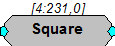
This component computes the mathematical square operation and passes the result to the output.
Equation:
Fo = Fi2
Example:
Smooth, Smooth.
StereoScale
Description:
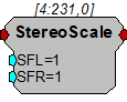
Scales a stereo signal. The left and right signals are scaled independently by SFL and SFR respectively.
StereoSum
Description:
Sums up to five stereo inputs and outputs one stereo signal.
Sum
Mult
Description:
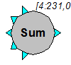
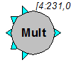
These multi-input components perform basic summing and multiplying functions. They work most efficiently when three or more inputs are used. Unused inputs will be ignored. All multiple inputs must come from primary outputs. If it is necessary to route a parameter output to this function, use a CONSTF to convert the signal to a primary output.
Equation:
Fo = Fi1 + Fi2 + Fi3 + Fi4 + Fi5
or
Fo = Fi1 * Fi2 * Fi3 * Fi4 * Fi5
Example:
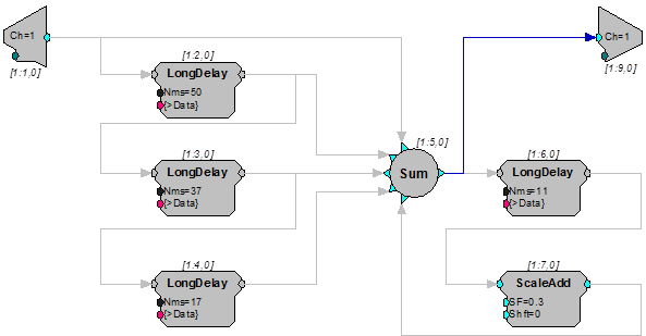
Sum - This construct implements a typical 'Reverb' circuit. The first three long delays are summed to simulate early reflections. The 4th delay is added back recursively to create the reverb chain. Try it out, it sounds like a big reverberant warehouse.