MultiProcessor Circuit Design
Overview
Multi-DSP architectures allow processing tasks to be distributed across several processors. This reduces the likelihood that the number of RPvdsEx components used on any one processor will exceed the processor's maximum (256 for RX processors, 768 for each RZ RZDSP processor, and 1000 for each RZ QZDSP). It also makes it possible to reduce the cycle usage demand on each processor, enabling each processor to run at a higher sample rate. Before attempting to design multi-processor circuits, it is a good idea to become familiar with the multi-DSP architecture of your device.
Assigning DSPs in RPvdsEx
A single RPvdsEx file must contain all the processing tasks for one device. Tasks can be split across DSPs to reduce individual processor load.
There are two methods available: using sheets or using DspAssign. When using either method, users should be familiar with the number of DSPs (and cores, if using a quad-core processor) available in their device and only assign tasks to those DSPs.
Using Sheets
In RPvdsEx the workspace is divided into tabbed sheets. The user can assign each sheet within the file to one or more processors or processing cores on that device. The circuit on that sheet will then run on the assigned processor or processing core. Multiple sheets can be assigned to the same processor or processing core. By default all sheets are assigned to the first or main processor.
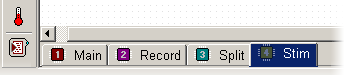
RZ RZDSP Processors
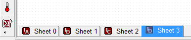
RZ QZDSP Processing Cores
RX Processors
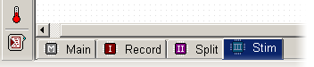
An icon on the sheet tab indicates which processor or core has been assigned, and if multiple processors or cores have been assigned.
For more information on assigning sheets to processors, see Assigning Sheets to a DSP.
Using DspAssign
The DspAssign component is specifically designed to designate a section of an RPvdsEx sheet to run on a processor or core other than the one assigned to that sheet. Paired with RPvdsEx macros, this component enables many multi-processor circuits to be displayed in a single sheet.
To use DspAssign, add it to the sheet then drag the borders to encompass the segment to be assigned to a different processor or core.
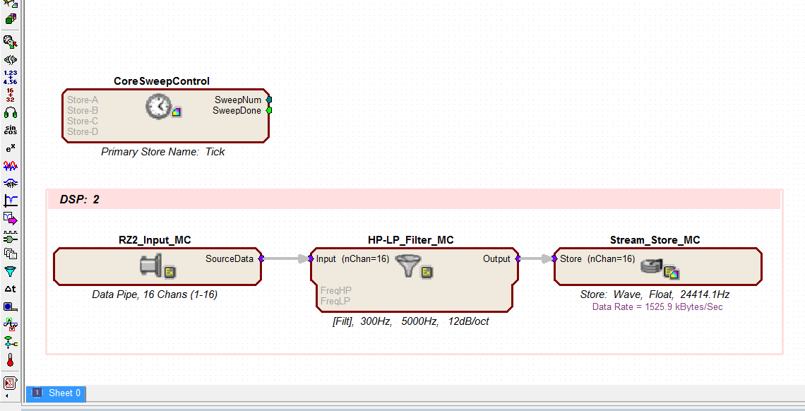
In the RX device circuit below, the CoreSweepControl macro runs on the Main DSP. The remainder of the components on the sheet are assigned by the DspAssign component to run on DSP Aux-1.
For more information, see DspAssign.
MultiProcessor Hop Components
The MultiProcessor Hop components are a special group of RPvdsEx components used to pass circuit signals between multiple processors. Signals are sent and received between DSPs via specialized hardware and these components.
- zHopOut moves a single channel signal to the zBus
- zHopIn retrieves a single channel signal from the zBus
- MCzHopOut moves a multi-channel signal to the zBus
- MCzHopIn retrieves a multi-channel signal from the zBus
- MCzHopPick retrieves a multi-channel signal from the zBus and outputs a single channel
Unlike the single processor HopIn and HopOut, each zHop compiles and is counted as a component that uses processing cycles. There is a consistent sample delay associated with these components to ensure known and consistent timing delays across multiple processors. The delay is one sample when used on an RX device or two samples when used on an RZ device.
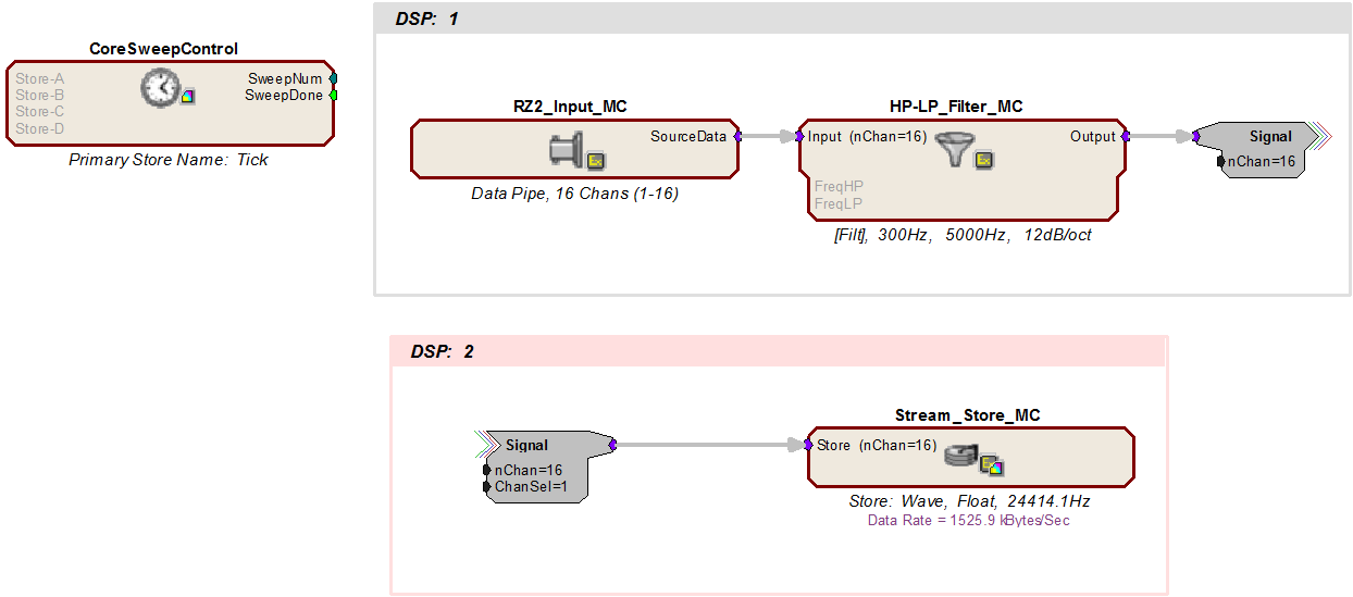
In the example above, a MCzHopOut feeds a 16 channel signal to a spike storage macro. All timing for the circuit is done on the main DSP processor while filtering and storage are done by separate (DSP: 1 and DSP: 2) processors. The DspAssign component splits the tasks while the zHop components make the signals available across multiple processors.
Using the {d} Variable
The variable d in braces, that is {d}, can be used to represent a number associated with the processor in any parameter or text label in a circuit. Values for the main and auxiliary processors of the RX devices are 0, 1, 2, 3 and 4 (max) respectively. Values for the RZ processors are 0 through 7 (max).
When the circuit is compiled the character d will take the value corresponding to the processor to which it is assigned. For example, if the channel number parameter for an AdcIn is set to {d}, and the sheet is assigned to the Aux-1 processor, then the channel number will be 1.
When a sheet is assigned to more than one processor, the variable can be used to yield different values for different processors. The {d} variable can also be used with formulas to yield the desired value.
For example:
A parameter value set to {1 + ((d- 1) * 16)} will take the values:
- 1 in the first auxiliary processor
- 17 in the second auxiliary processor
- 33 in the third auxiliary processor
- 49 in the fourth auxiliary processor
Note
This formula is suitable for the RZ processors and the RX auxiliary processors but cannot be used on processors with a value of 0 or on quad-core DSPs.
Store Pooling
Store Pooling is a special feature of some data storage macros targeted for TDT's OpenEx software suite. When groups of channels from a larger multi-channel signal are processed and stored using different processors on a multi-processor device, Store Pooling serves to identify stored data as being part of a larger whole.
For example:
If channels 1 - 16 of a 32 channel signal are stored using a data storage macro on DSP-1
And channels 17 - 32 are stored using a data storage macro on DSP-2
Store Pooling ensures all 32 channels appear to be one "Data Store" in the OpenEx DataTank.
See the internal macro help of the data saving macros for more information on using Store Pooling.
Multi-Processor Circuit Design Strategies
When designing circuits for multiprocessor devices, users should employ strategies that take advantage of the distributed processing made possible by the multi-DSP architecture and the MultiProcessor components available in RPvdsEx. These strategies typically include organizing the circuit into logical units by task and distributing tasks across processors. For high-channel count applications this might include distributing data storage across multiple processors.
So, a 64 Channel Spike Sorting circuit might be distributed as follows:
DSP-1: timing and control
DSP-2: process and store 16 channels
DSP-3: process and store next 16 channels
DSP-4: process and store next 16 channels
DSP-5: process and store next 16 channels
When distributing processing tasks across multiple processors, users must always consider:
- The limitations of each processor.
- The multi-DSP architecture of the device.
Each processor:
- Has a finite amount of processing power dependent on sampling rate.
- Each processor may be assigned up to 256 components for RX processors and 768 for RZ processors and 1000 for RZ QZDSP processor cards.
The number of components on each processor is reported by RPvdsEx after compiling the circuit, and the cycle usage of each processor is reported on the front panel display of the devices.
Device architecture:
RX devices rely on the Main processor to handle all communications. When using an RX device TDT recommends keeping the processing tasks assigned to the Main processor light, freeing it up to handle communications and data transfer more efficiently.
Multi-Processor Circuit Design - RZ2
The RZ2 processor has a unique architecture that includes a "Pipe Bus" not available in RX or other RZ devices. It supports simultaneous acquisition on 256 channels at sampling rates up to ~25 kHz and up to ~50 kHz on up to 128 channels.
Multi-processor Pipe Components
The Multi-Processor components are a special group of RPvdsEx components used to pass circuit signals between multiple processors on the RZ2. These signals are shared or passed between DSPs using either the Data Pipe Bus or the zHop Bus. Pipe components move data most efficiently across the Data Pipe Bus. There is a consistent two-sample delay associated with these components to ensure known and consistent timing delays across multiple processors.
- PipeSource feeds up to 256 channels to a DSP's pipe input, either directly from a preamplifier, via the optical input port, or from another DSP
- PipeIn retrieves a single channel signal from a DSP's pipe input
- PipeOut moves a single channel signal to a DSP's pipe output
- MCPipeIn retrieves a multi-channel signal from a DSP's pipe input
- MCPipeOut moves a multi-channel signal to a DSP's pipe output
Typically, all high channel count connections on the RZ2 are made using the Pipe components. However, the RZ2's zHop Bus does support up to 126 zHop pairs.
The zHop components were designed to pass arbitrary control and data signals between DSPs in the RX systems and are more commonly used with RX processors.
See MultiProcessor Hop Components, for more information.
Designing Multi-processor Circuits for the RZ2
When working with RZ2 devices the user should be aware of the following:
- The RZ2_Input_MC macro is the best method for inputting signals using the RZ2. Every DSP that uses the pipe bus must have a PipeSource component. There is a checkbox in the RZ2_Input_MC macro that inserts this for you, or you must manually place one in the circuit for that DSP.
- DSPs do not share memory as with RX devices, so circuits that rely on memory sharing will have to be modified to run on the RZ2 processor.
- While sample rates from 6 kHz to 50 kHz are supported, each fiber connection on the RZ2 can only support 128-channels when sampling at 50 kHz. While sampling at 50 kHz:
Only the first 128 BioAmp channels will be available per fiber optic port.
All Data Pipes will have a max of 128 channels instead of 256.
Both halves (A and B) of the PipeSource component must be selecting the desired source. For example, when acquiring data from a PZ preamplifier, Pipe[A] and Pipe[B] both need to be set to Amp. Chan[1..128].
- As with other devices, your expected sustained RZ-to-Host PC data rate should not exceed 1/2 to 2/3 of the rated data transfer speed. For the RZ2 device this is 160 Mbits/second (Mbps) so your designs should have a sustained data rate of no more than ~100 Mbps. This maximum rate may be further limited by your PC's ability to store the data to disk.
When working with QZDSP quad-core processors on an RZ device the user should be aware of the following:
- QZDSP processor cores do not share memory.
- RZ QZDSP processors rely on core-A for communication with the Pipe Bus and any associated optical port. When accessing the Pipe bus from a QZDSP, the PipeSource component must be placed on each of the cores, but only the PipeSource on core-A defines the actual source while the source in the other PipeSource components is ignored. The PipeSource component must be on each core whether it's using a pipe input, output, or both.
- Pipe bus output is limited to 256 channels per QZDSP card. Users can split up groups of channels to assign to different cores, but should not assign 256 channels to more than one core.
Example: RZ2 - 16 Channel Spike Sorting
In the following example, a multi-processor circuit acquires and filters 16 channels of data acquired using the RZ2 processor and PZn BioAmp. When using the PZn, signals are carried from the BioAmp across a high speed fiber optic cable to the RZ2's Optical Port where the I/O interface routes signals to the Pipe Bus. Once on the Pipe Bus, data is available to all DSPs.
The circuit supports spike sorting and stores sorted spikes and streamed data.
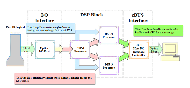
These tasks are split across three processors with multi-processor RPvdsEx components that efficiently pass the data between DSPs at different stages of processing. The flow and circuit diagrams below show how the signals are moved through the processor based on the bus architecture and the circuit design.
Timing and Control
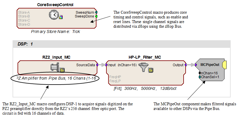
In the diagram above, blue arrows show how some signals are being distributed across the DSP Block, from DSP-1 to DSP-2 and DSP-3, via the zHop bus. The CoreSweepControl macro in the diagram below produces core timing and control signals required in all circuits designed for use with TDT's OpenEx software. These signals, such as enable and reset, are used throughout the circuit and are distributed via zHops (this is handled within the macro and is transparent to the user). Although the zHop Bus is a less efficient method for handling high channel count data, it is suitable for this type of data transfer.
Acquisition and Filtering
In the circuit segment above, DSP-1 acquires and filters raw data from a Z-Series BioAmp across the Pipe Bus. The RZ2_Input_MC macro handles all the tasks associated with acquiring signals using the RZ2, including making the necessary data type conversion and applying the correct scale factor for display and analysis. Because scale and channel offsets vary for different types of RZ2 inputs, the user must select the type of input within the macro Setup properties.
Macro setup properties...
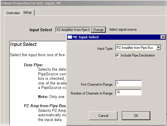
When needed, an MCPipeIn is automatically included within the RZ2_Input_MC macro, but the user must select the Include Pipe Declaration check box in the macro's MC Input Select dialog box to automatically place the PipeSource. The circuit for each DSP that includes any of the pipe input or output components must also include one and only one PipeSource component. The PipeSource declaration may be added internally (automatically by the macro) or externally (manually added outside of the macro).
Once configured, the RZ2_Input_MC macro feeds the circuit with the first 16 channels of data. The HP-LP_Filter_MC macro filters all 16 channels through cascaded highpass and lowpass filters. MCPipeOut makes the filtered multi-channel signal available to other DSPs via the Pipe Bus.
Storing Streamed Data
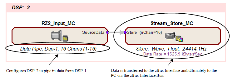
On DSP-2, the RZ2_Input Macro is used to feed the processor with data from the Pipe Bus.
Note
This can also be accomplished using the PipeSource and MCPipeIn components.
In this example, the RZ2_Input Macro is used to configure DSP-2 to pipe in filtered data from DSP-1 across the Pipe Bus. It routes 16 channels of acquired and filtered signals to the Stream_Store_MC macro for data storage. Data is then transferred to the zBus Interface and ultimately to the PC via the zBus Interface bus, as indicated by the green arrows in the previous flow diagram on Example: RZ2 - 16 Channel Spike Sorting. The following diagram illustrates the DSP-2 configuration.
Spike Sorting and Snippet Storage
On DSP-3, the RZ2_Input Macro again configures the DSP to pipe in data from DSP-1. It routes 16 channels of acquired and filtered signals to the Spike_Store_MC macro for spike sorting and data storage. This macro can be set to use one of several supported sorting methods. Again stored data is transferred to the zBus Interface and ultimately to the PC via the zBus Interface bus.
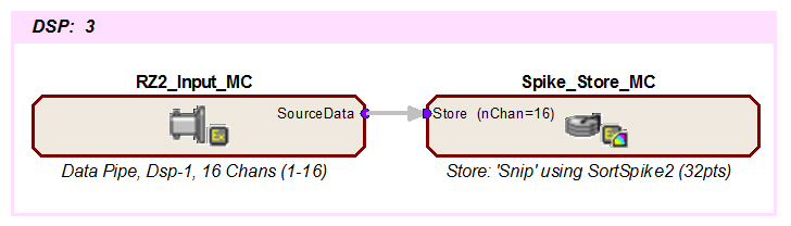
This simple circuit acquires, filters, processes and stores 16 channels of data.