Basic Analysis
Components in the Basic Analysis group analyze various aspects of a signal.
This group includes the following components:
This group also includes the following component, if RPvdsEx Device Setup is configured for a high performance device, such as the RXn or RZn:
FeatSrch
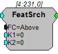
Description:
A feature search looks for a particular set of criteria to be reached. When the criteria are met the feature search component generates a logical high (1) otherwise a logical low (0) is generated. Users choose fixed criteria for the search (e.g. the input is between two values). The condition levels can be changed while the circuit is running.
The possible feature search codes are:
OFF No search in progress (output is always 0)
ABOVE Checks to see if the input is above K1
BELOW Checks to see if the input is below K1
BETWEEN Checks to see if the input is above K1 and below K2
OUTSIDE Checks to see if the input is below K1 or above K2
RISING Checks to see if the input is rising
FALLING Checks to see if the input is falling
PEAK Checks to see if the input rose and then fell
VALLEY Checks to see if the input fell and then rose
TIP Checks to see if the PEAK or VALLEY event has occurred
RISETHRU Checks to see if the input has risen through K1
FALLTHRU Checks to see if the input has fallen through K1
PASSTHRU Checks to see if the RISETHRU or FALLTHRU event has occurred
Example:
Feature Search
File: Example\FeatSrch.rcx
Default Device: RP2 Processor
Sampling Rate: 50 kHz
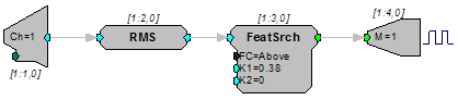
This example implements a simple signal detector. It calculates the RMS of the input and FeatSrch sends a TTL pulse to the BitOut when the RMS goes above 0.38. To save the signal that comes in, modify the circuit with a Serial Buffer.
Note
Additional circuitry is included in the example file to demonstrate how the example works.
FindFreq
Description:
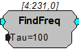
FindFreq calculates the frequency of a signal using zero-crossings. Tau is the number of milliseconds over which the zero-crossing is calculated.
PowerBand
Description:
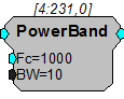
This component computes the power of the input signal within the specified band. Power is defined as the integral (area under the curve) of that bandwidth. The time it takes to calculate the PowerBand is inversely related to the bandwidth, i.e. a 1 Hz bandwidth takes 1 second while a 0.1 Hz bandwidth takes 10 seconds. To calculate level, you would take the square root of the output.
Example:
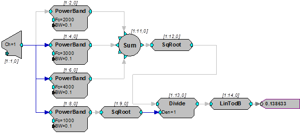
Power Band - This circuit builds a THD (Total Harmonic Distortion) measurement system. The signal applied to A/D channel one is passed through four PowerBand components. The power measured at the first three distortion components is summed and converted back to RMS via the SqRoot processor. The fundamental is also measured and converted to RMS. The two RMS results are then compared via Divide and converted to a dB ratio with LinTodB. This analyzer can measure THD ratios down to about 90 dB.
RMS
Description:
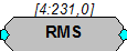
This component computes the RMS value by squaring the input, lowpass filtering the input data, and taking the square root.
Note
The RMS component has a built-in time constant (tau) of 1 second.
Equation:
Output = RMS (Input)
Example(s):
Feature Search, FeatSrch.
RMS2
Description:
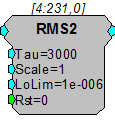
RMS2 calculates an approximate RMS value of the input signal with a moving average filter to disregard spurious signals that are in excess of 3X the running average. The lowest possible output of this component is set by LoLim and the smoothing average time constant is set by Tau. Reset forces the output to LoLim and restarts the averaging process. This component has been optimized to improve cycle usage for multi-channel use and should only be used for neural signals with a Gaussian probability, not sinusoidal signals. The LoLim value should match the experimental threshold and with each reset, the output will begin deviating from this value at a rate not greater than 1.3X LoLim per unit of time defined in Tau.
Note
This component is for use with only high performance processor devices, such as RXn or RZn.
TrackMax
Description:
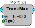
Tracks the maximum value of an input until the reset is triggered. When reset (Rst=1), the maximum value is reset to Vi. This function is useful for measuring peak amplitudes in signals.
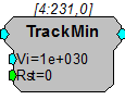
TrackMin
Description:
Tracks the minimum value of an input until the reset is triggered. When reset (Rst=1), the minimum value is reset to Vi. This function is useful for measuring trough amplitudes in signals.