Coefficient Generators
The Coefficient Generators components are used to calculate the coefficients of specified high-pass, low-pass, band-pass, or notch filters in real-time. Their outputs can be connected to the filter coefficient port of a Biquad filter component.
Note
Coefficient generator components are designed to be used with a single filter component. Do not use a single coefficient generator component with multiple filter components.
This group includes the following components:
ButCoef
Description:
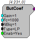
This component generates the coefficients for an Nth order Butterworth filter (highpass or lowpass) having the specified attributes for the Biquad filter. New coefficient values are generated whenever the enable line (Enab) is high (1). Setting the enable line to low (0) after the coefficients have been generated decreases cycle usage. The ButCoef can also be placed in time slice -1 to generate the coefficients only once. The coefficients will be generated when the processing chain is run and will remain unchanged during acquisition, further reducing cycle usage. To generate coefficients for notch or bandpass filters, use ButCoef1.
Note
To satisfy the Nyquist Theorem, the sampling frequency of the system should be greater than 2 times the highest frequency component passed by the filter.
Tech Note
Clipping (when voltage value is greater than the DAC can handle) will occur when the Gain of the ButCoef to the input signal produces a voltage value larger than ± 10 and is sent to a D/A for play out. Check the output values of the filtered signal to determine if this is a problem.
Example:
Second Order Biquad Filter
File: Examples\ButCoef_ex.rcx
Default Device: RP2 Processor
Sampling Rate: 50 kHz
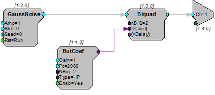
This example uses a ButCoef to create a second order biquad filter, with a 2000 Hz high-pass, and generates filtered noise. Notice that nBIQ has been set to two for both the Biquad and ButCoef components.
ButCoef1
Description:
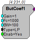
This component generates the coefficients for a second order Butterworth filter (lowpass, bandpass, highpass, or notch) having the specified attributes for the Biquad filter. When using a bandpass or notch filter, the BW (bandwidth) parameter refers to the filter bandwidth at 3dB attenuation (e.g. for Fc = 5 kHz and BW = 1 kHz, the 3dB attenuation would occur at 4.5 kHz and 5.5 kHz). When the filter type is set to LP (lowpass) or HP (highpass), the BW parameter is redundant and is ignored.
New coefficient values are generated whenever the enable line (Enab) is high (1). Setting the enable line to low (0) after the coefficients have been generated decreases cycle usage. The ButCoef1 can also be placed in time slice -1 to generate the coefficients only once. The coefficients will be generated when the processing chain is run and will remain unchanged during acquisition, further reducing cycle usage.
ButCoef1 allows the user to build only lower order filters. Multiple filters can be cascaded to make higher order bandpass and notch filters. To generate coefficients for higher order lowpass and highpass filters users should use ButCoef.
Note
To satisfy the Nyquist Theorem, the sampling frequency of the system should be greater than 2 times the highest frequency component passed by the filter.
Tech Note
Clipping (when voltage value is greater than the DAC can handle) will occur when the Gain of the ButCoef1 to the input signal produces a voltage value larger than ± 10 and is sent to a D/A for play out. Check the output values of the filtered signal to determine if this is a problem.
Example:
Butterworth Coefficients
File: Examples\ButCoef1_ex.rcx
Default Device: RP2 Processor
Sampling Rate: 25 kHz
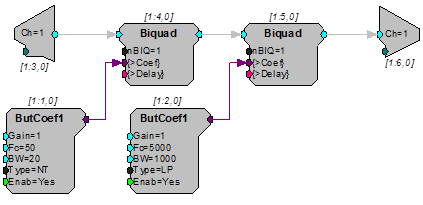
This example uses two ButCoef1 generators to filter the signal input. The first ButCoef1 generates a 50 Hz notch filter and the second generates a 5000 Hz low-pass filter. The filtered signal is sent to D/A channel one. Note that the number of Biquads (nBIQ) is one.
CoefLoad
Description:
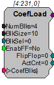
The CoefLoad component is used to quickly load and update component coefficients at run-time under user control. Uses include updating filter coefficients and channel mappings. Using this component extends the usefulness of components like FIR2 by allowing many more blocks of coefficients to be used. These blocks are stored in the much larger XM memory area and then loaded to the smaller PM memory when needed.
Because the coefficients are loaded one at a time on each tick of the sample clock, when a new coefficient set is needed, it will take BlkSize+1 cycles to load (BlkSize equals the number of coefficients being loaded). This time delay is typically not an issue. The CoefLoad component has an optional FlipFlop output that can be used to drive the block select input of the loaded component. The ActCnt output is used to determine if there are more coefficients to be loaded. If ActCnt > 0, the component is active and is in the process of loading coefficients.
Coefficient blocks within this component can have any format and any arrangement. However, this arrangement must match the needed format and arrangement of the target component. The blocks of coefficients are then simply placed sequentially in the component's XM memory.
Example:
Load Coefficients
For setting arbitrary channel mappings using the MCMap component:
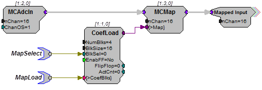
This circuit supports four channel mappings on the 16 channel input signal. The MapLoad tag must be loaded with the channel mappings before the MapSelect parameter is set. In this case, the loaded values would be 32 bit integers arranged in four blocks of 16 values each.
Note
EnableFF = No for this application.
To dynamically update the coefficients of a filter:
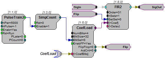
This circuit supports the loading of 4 different sets of coefficients into the FIR2 filter component. Each block contains 32 filter taps arranged as specified by the FIR2 component description. Every 5000 ticks of the sample clock, the PulseTrain2 will advance the SimpCount counter causing the next filter set to be loaded and selected (via the FlipFlop control). It is important that the SimpCount output does not exceed NumBlks and that the nPer argument in PulseTrain2 is not set less than BlkSize +1.
ParaCoef
Description:
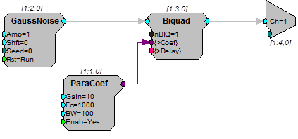
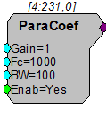
This component generates the parametric coefficients for a second order equalizing Biquad filter. Center frequency (Fc) and bandwidth at 3 dB (BW) are specified by the user and the band gain increases the intensity of the signal within the band by the linear scale factor (gain) specified. The gain value should be set carefully to ensure that the amplified signal will not exceed the dynamic range (typically ± 10 V) of the processor module. When a unity gain (Gain = 1) is specified, coefficients for an all pass filter are generated.
The table below lists typical roll-offs from the center frequency for several gain settings.
New coefficient values are generated whenever the enable line (Enab) is high (1). Setting the enable line to low (0) after the coefficients have been generated decreases cycle usage. The ParaCoef can also be placed in time slice -1 to generate the coefficients only once. The coefficients will be generated when the processing chain is run and will remain unchanged during acquisition, further reducing cycle usage.
Note
To satisfy the Nyquist Theorem, the sampling frequency of the system should be greater than 2 times the highest frequency component passed by the filter.
Tech Note
Clipping (when voltage value is greater than the DAC can handle) will occur when the Gain of the ParaCoef to the input signal produces a voltage value larger than ± 10 and is sent to a D/A for play out. Check the output values of the filtered signal to determine if this is a problem.
Example:
Parametric Coefficient
File: Examples\ParaCoef_ex.rcx
Default Device: RP2 Processor
Sampling Rate: 50 kHz
This example uses the ParaCoef generator with a Biquad to filter a band of noise 100 Hz wide centered at 1000 Hz. The gain is set to 10 dB to increase the output level of the filter. Parametric filters act like equalizers on an amplifier.