Waveform Generators
Waveform Generators are components that generate signals on the DSP. Almost any signal can be produced by combining these basic waveform generators with filters and signal mixers.
This group includes the following components:
This group also includes the following components, if RPvdsEx Device Setup is configured for a high performance device, such as the RXn or RZn:
ConstF
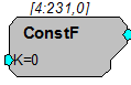
Description:
This component feeds the signal chain with the specified constant. Often used with parameter tags, which are unable to connect to the input port of a processor.
Equation:
OutputO = K1
ConstI
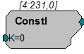
Description:
This component feeds the signal chain with the specified constant. Often used with parameter tags, which are unable to connect to the input port of a processor.
Equation:
OutputO = K1
ConstL
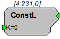
Description:
This component feeds the signal chain with the specified constant. Often used with parameter tags, which are unable to connect to the input port of a processor.
Equation:
Fo = K1
FStep
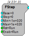
Description:
The FStep is an up/down counter. It counts for the duration of a high pulse sent to the Enable port ( Enab ). It increments the count by a set value (determined by Step) for each pulse of sample clock (e.g. if the enable is high for 1 msec and the sample rate is 25 Kilohertz then the counter will step 25 times). When it reaches the Min or Max value the FStep stops and retains that value until reset (see below for more details). The FStep starts at the Base value the first time the counter is started or after the Reset (Rst) port is triggered (value goes from low (0) to high (1)).
Use FStep in place of Counter (which is primarily designed for RamBuffers) for functions that require countdown, negative numbers, or floating point output.
GaussNoise
Description:
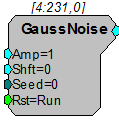
This component generates a white noise process with a Gaussian probability density function with the specified attributes. Peak voltages will be higher. To avoid clipping a signal the RMS amplitude should be less than 2.1.
All noise generators produce a fixed energy across the bandwidth of the RPvdsEx circuit. In other words, the noise power is spread evenly across the entire Nyquist bandwidth. Changing the sampling rate changes the Nyquist bandwidth and thus alters the RMS noise level over a fixed bandwidth by the following relationship:
RMS dB change=20*log(New SR/Old SR)/2
Doubling the sample rate will double the Nyquist frequency and decrease the RMS noise level over a fixed bandwidth by 3 dB. Similarly, halving the SR will increase the RMS over that bandwidth by 3 dB.
Note
The PowerBand difference will be 6dB.
Example(s):
Second Order Biquad Filter (filtered noise with Butterworth coefficients), see ButCoef.
Parametric Coefficient (filtered noise with parametric coefficients), see ParaCoef.
MCConst
Description:
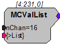
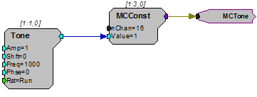
This component is a multi-channel version of the ConstF component. MCConst feeds a specified constant to a multi-channel output. The constant is specified using the Value parameter and can be controlled dynamically. The constant is fed to each of the signals in the multi-channel signal. The number of channels in the output is specified by the nChan parameter.
Note
This component is for use with only high performance processor devices, such as RXn or RZn.
Equation:
Output(1: nChan) = Value
MCValList
Description:
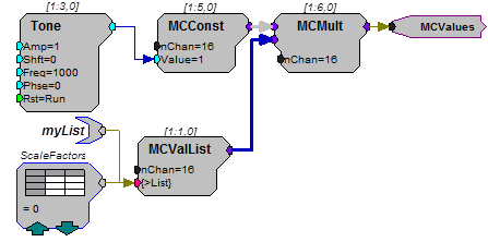
This component is similar to MCConst but lets you specify the value for each individual channel. MCValList feeds a specified list to a multi-channel output. The value list is specified using the {>List} parameter and can be controlled statically with an nRow DataTable or dynamically with a ParTag. The number of channels in the output is specified by the nChan parameter.
Note
This component is for use with only high performance processor devices, such as RXn or RZn.
Equation:
Output(1: nChan) = {>List}
PulseGen
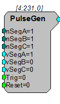
Description:
PulseGen is a three segment pulse generator with all timing specified in samples. All setup parameters can be controlled dynamically. The Trig input triggers the pulse. The Reset input can be used to asynchronously halt the pulse generator. To produce continuous pulses, set and hold Trig to 1. To produce a set number of pulses, connect a PulseTrain2 component to the Trig input.
Note
This component is for use with only high performance processor devices, such as RXn or RZn.
RampTooth
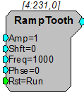
Description:
This component generates a ramped waveform with the specified attributes.
Note
Ensure that the bounds of the phase parameter are greater than -180 and less than +180. Any value (including exactly -180 or +180) outside of these bounds will be set to a phase of zero.
Random
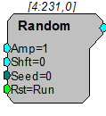
Description:
This component generates a white noise process with a uniform probability density function with the specified attributes. The amplitude specifies the maximum output of the component.
All noise generators produce a fixed energy across the bandwidth of the RPvdsEx circuit. In other words, the noise power is spread evenly across the entire Nyquist bandwidth. Changing the sampling rate changes the Nyquist bandwidth and thus alters the RMS noise level over a fixed bandwidth by the following relationship:
RMS dB change=20*log(New SR/Old SR)/2
Doubling the sample rate will double the Nyquist frequency and decrease the RMS noise level over a fixed bandwidth by 3 dB. Similarly, halving the SR will increase the RMS over that bandwidth by 3 dB.
Note
The PowerBand difference will be 6dB.
SawTooth
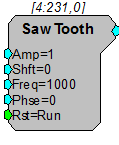
Description:
This component generates a saw tooth waveform with the specified attributes.
Note
Ensure that the bounds of the phase parameter are greater than -180 and less than +180. Any value (including exactly -180 or +180) outside of these bounds will be set to a phase of zero.
Tone
Description:
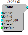
Generates a sinusoid Waveform with the specified frequency and phase. The waveform's Amplitude and DC Shift can also be controlled. The Rst control is used to reset the signal's phase. The output will remain locked at the specified starting Phase as long as Rst is high. Typically an Edge Detector is used in conjunction with the Rst control.
Note
Ensure that the bounds of the phase parameter are greater than -180 and less than +180. Any value (including exactly -180 or +180) outside of these bounds will be set to a phase of zero.
Example:
This example demonstrates a number of circuit design concepts as well as the use of the Tone component. The circuit shown will generate an AM modulated sinusoidal output from channel one of the DAC. The output will be 100% modulated with a peak voltage of 2.0 volts.
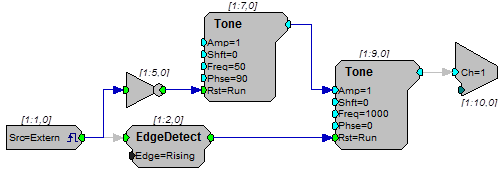
The external trigger input is used to turn the output on and off by driving the Rst control of the modulator tone. Notice that the phase for the modulator tone is specified as -90 degrees causing it to fully 'close' when the reset line is high (trigger input is low).
The carrier tone is set for 1000 Hz output. The default value of Amp = 1.0 will be ignored as this parameter is being dynamically controlled by the modulator tone. The carrier's Rst is fed by an edge detector connected to the external trigger. This forces the carrier to start at sine phase 0.0 each time the external trigger is high.
TSlope
Description:
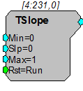
This component generates a linear ramp waveform with the specified attributes. It is useful for generating a time value for time stamping buffer operations.