Audio Processing
The Audio Processing group includes components that are related to 3D audio processing. This section also includes information about the HRTF file format used by TDT.
This group includes the following components:
HRTF File Format
 The following information gives a general overview of HRTFs and the file format for using custom HRTF coefficients.
Introduction
An HRTF (Head Related Transfer Function) contains all the listening cues that are applied to a sound as it travels through the environment to arrive at the ear. The signal at the ear will depend on the azimuth, elevation and distance of the source relative to the ears. A complete set of HRTFs consists of many filters that describe a spherical map of the possible sound sources. The HRTF contains information about frequency dependent sound delays and intensity differences between ears. When a signal is sent through an HRTF filter and then played through headphones the listener receives the impression of where the sound source should be.
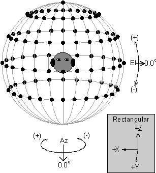
In the illustration each point represents a sound source. The distance of the source is a constant relative to the center of the head. Sources can change in the lateral position around the head (Azimuth) or the elevation of the source relative to the ears. In general, differences in delay and intensity between ears for a given sound change most in the Azimuthal position and less so for elevation. These differences are frequency dependent.
Values can be sent to the RPvdsEx HRTF component coefficient for Azimuth and Elevation. The HRTF coefficient processor finds the proper coefficients in a look up table on a Ram Buffer component, interpolates the values and sends them to the HRTF filter. This produces real-time virtual 3-D audio processing on the RP. Output of the processor can be fed to the HRTF filter processor. HRTF coefficients are organized in the following file format for retrieval by the HRTF filters.
The filter coefficients are loaded into a RAM buffer large enough to hold all the coefficients. The component number of the RAM buffer is stored on the HRTF coefficient processor. It is possible to have several sets of HRTF coefficients in different Buffers and switch between them. Information about the organization of the HRTF is given in the header section. The following format is required for the header.
HRTF Header Format
A 90 degree filter value must be specified for the Maximum_El value.
Resolution values are defined as the inverse of the AZ or EL separation.
HRTF Filter Organization
Filter coefficients are grouped first according to their elevation from maximum elevation to minimum (e.g. 90, 60,...-60, -90). For each elevation the filters are organized from maximum AZ to minimum AZ values (e.g. 180, 165,...-165). The table below gives an example of the filter organization.
Important
Even if there are no values for elevation of 90 degrees a dummy set of filter values must be included.
HRTF Filter Coefficient Format
The coefficient values for the HRTF must have the following format. They must be minimum-phase with the left and right channels interleaved. Filter values are stored as 32-bit floats with the filter's group delay stored as the last element of the filter. The example below shows the file format for a 31 tap left/right filter pair. The HRTF FIR filter requires that the order include the delay.
All Coefficients and delays are 32-bit floating point values. The delays are specified in number of samples.
The order of the filter must include the number of taps and the delay. A filter order of 32 has 31 taps and 1 group delay.
The MaxITD value must be greater than the maximum delay specified for any filter to be used and is fixed at the start of the circuit.
DistScale
Description:
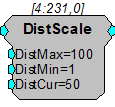
Scales signal to model attenuation with distance. The DistCur is limited to the DistMin and DistMax specified. Then the signal is scaled by DistMin/DistCur.
HrtfCoef
Description:
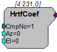
HrtfCoef obtains coefficients from the memory of CmpNo. Azimuth and Elevation inputs can be dynamically changed to switch between azimuth and elevation-specific HRTFs. It will interpolate between sets of coefficients as Azimuth and Elevation are changed. RPvdsEx comes with a set of HRTFcoef.
For more about custom HRTF filters see HRTF File Format.
Example(s):
3D Circle, Reverb.
HrtfFir
Description:
FIR filter using HRTF coefficients. Filter coefficients can be obtained by connecting the HrtfCoef component to the >Coef pointer on HrtfFIR. Custom filter processing can be done by using the >Coef and >Delay lines.
The Order of the filters is equal to the number of taps (per ear) plus the delay value (ITD). A 31 tap filter will have a filter order of 32.
The maximum ITD (Interaural Time Delay) is static and must exceed the maximum value from any of the filters.
RPvdsEx comes with HRTF filters. Information about using custom filters can be found in HRTF File Format.
Example(s):
3D Circle, Reverb.
Reverb
Description:
The reverberation component (Reverb) can be used to obtain more realistic spatialization of 3D sound.
Example:
3D Circle
File: Examples\3D_Sound\3d_circle.rcx
Default Device: RP2 Processor
Sampling Rate: 50 kHz
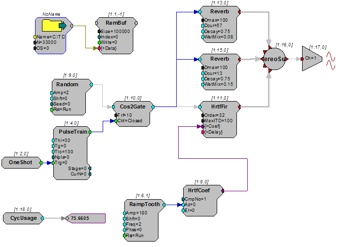
This example implements a basic 3D application. The circuit generates a pulsed sound and filters it through dynamically changing HRTF filters. The processor is also controlling the trajectory of the sound. A RampTooth generator is used to produce the appropriate azimuth values to make the sound circle the head. The pulsed sound could easily be replaced by audio inputs to the processor.
Note
High-quality headphones should be used to reproduce the 3D spatialization effect. The 3D sound effect will not be heard over speakers.
Example:
FlyBy
File: Examples\3D_Sound\flyby.rcx
Default Device: RP2 Processor
Sampling Rate: 50 kHz
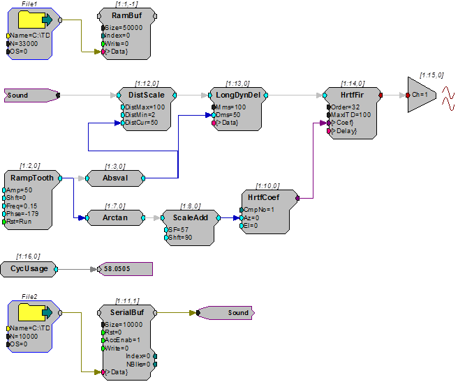
This example shows how to implement a flyby. A short helicopter.wav file is loaded into the circuit and then run through processing that adjusts sound level, direction, and Doppler shift based on distance. The DistScale component is used to control sound level as a function of distance. The LongDynDel component is used to generate the Doppler shift. The HrtfCoef and HrtfFir components are used to change the apparent azimuth of the helicopter as it flies by.
Note
High-quality headphones should be used to reproduce the 3D spatialization effect. The 3D sound effect will not be heard over speakers.