Digital Filters
Digital Filter components perform basic digital filtering tasks. Coefficients can be pre-loaded or generated and updated on-the-fly. See Coefficient Generators, for information on dynamically changing filter performance.
Note
To satisfy the Nyquist theorem, the filter's corner frequency should always be less than half the sampling frequency.
This group includes the following components:
This group also includes the following components, if RPvdsEx Device Setup is configured for a high performance device, such as the RXn or RZn:
Biquad
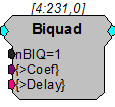
Description:
This component filters the input with an Nth stage Biquad. nBiq can be from one to 16 and care must be taken to match the number of stages with whatever coefficient generation scheme you are using. The Coefficient buffer is [ nBIQ *5] in length and is kept in PM. A delay line of length [ nBIQ *4] is held in DM. Each digital filter needs its own coefficient generator. Biquad accepts coefficient inputs from the filter coefficient generators.
Coefficients can be generated using one of the Coefficient Generator components or supplied via parameter tag (for example, when generated using the Biquad Coefficient Control in OpenController software).
Note
Filter frequencies should be less than half the sampling rate of the system.
Equation:
Fo = Biquad(Fi)
Example:
Biquad Filter
File: Examples\BiquadEx.rcx
Default Device: RP2 Processor
Sampling Rate: 50 kHz
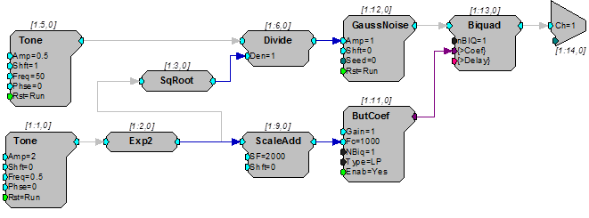
This somewhat complex circuit demonstrates a number of processing concepts, including the Biquad filter and the ButCoef, a Butterworth coefficient generator with specific attributes for the Biquad filter. The circuit generates filtered amplitude modulated noise for D/A channel one. The noise is low-pass filtered using a Biquad with the filtering coefficients being generated in real-time via the ButCoef component. Because the coefficients are generated in real-time the low-pass filter frequency can be changed dynamically.
The Tone generator at chain position [1:1,0] is used to modulate the filter corner frequency by octaves. The Exp2 component converts the octave output to a linear multiplier that is then scaled by 2000 via ScaleAdd. This generates a sinusoidal non-linear frequency sweep that goes from two octaves (500 Hz) below to two octaves (8000 Hz) above 2000 Hz.
The Tone generator at [1:5, 0] is used to modulate the amplitude of the noise to a depth of 50%. SqRoot and Divide are used to normalize the level of the circuit's output so it won't get louder as the bandwidth gets wider.
FIR
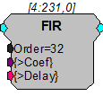
Description:
This component filters the input with an Nth order FIR. The Order must be specified as at least 1 and not more than 1024. Two memory buffers are associated with FIR. The Coefficient buffer is [ Order +1] in length and is kept in PM. A delay line of length [ Order +1] is held in DM. Each digital filter needs its own coefficient generator.
Coefficients can be generated using one of the Coefficient Generator components or supplied via parameter tag (for example, when generated using the Biquad Coefficient Control in OpenController software).
Note
Filter frequencies should be less than half the sampling rate of the system.
Equation:
Fo = FIR(Fi)
Example:
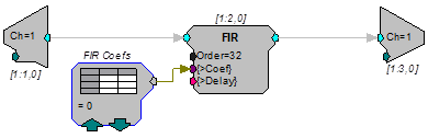
FIR/Data Table - This example uses an FIR filter to alter the input signal. The FIR filter coefficients are loaded into a DataTable. The input of ADC channel one is filtered by the 33 tap FIR filter and played out of the DAC. The contents of the DataTable can be loaded with FIR filters generated from MATLAB.
FIR2
Description:
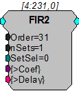
The FIR2 is a single channel, optimized FIR filter that supports multiple filter coefficient sets.
This component filters the input with an Nth order FIR. Order must be specified as at least 5 and should always be odd (nTaps will be even). Two memory buffers are associated with FIR2. The Coefficient buffer is [( Order +1)*nSets] in length and is kept in PM. A delay line of length [ Order +1] is held in DM. FIR2 supports instant coefficient switching through (zero-based) SetSel. Note that the FIR Coefficient Data Table may not be used with the FIR2 component.
SetSel is used to specify the coefficient set to use. This input can range from 0 to nSets-1. Setting this input to a value outside this range will cause your circuit to fail.
All of the xxFIR2 components allow for a unique set of coefficients for each channel (when more than one channel is applicable) and instantaneous switching between coefficient sets using the SetSel input. Also longer filters can be specified. While there is a hard limit on the filter order of 8191, this value is more often limited by the amount of PM memory available for the filter. When specifying an FIR2 type filter, pay special attention to any loading or memory allocation errors that are generated when your circuit is loaded.
Note
This component is for use with only high performance processor devices, such as RXn or RZn.
Note
Filter frequencies should be less than half the sampling rate of the system.
Equation:
Fo = FIR(Fi)
Coefficient
Ordering:
To optimize performance the FIR2 component requires each coefficient set be arranged into a shuffled format. Each coefficient set must be shuffled as follows:
n = nTaps = Order + 1
B0, Bn/2, B1, Bn/2+1 ... Bn/2-1, Bn-1
For Example:
Order = 9
nSets = 3
Filter coefficients in logical order:
The coefficients must be shuffled as follows:
The coefficients are then concatenated and loaded as a row vector as follows:
Coef = [Set1, Set2, Set3]
FIR2D
Description:
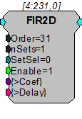
The FIR2D component is identical to FIR2, except it has an additional Enable input. The filter is only active when Enable is high. This lets you create a lower frequency FIR filter with fewer taps.
Note
This component is for use with only high performance processor devices, such as RXn or RZn.
FIRD
Description:
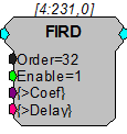
The FIRD component is identical to FIR, except it has an additional Enable input. The filter is only active when Enable is high. This lets you create a lower frequency FIR filter with fewer taps.
Note
This component is for use with only high performance processor devices, such as RXn or RZn.
IIR
Description:
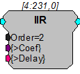
This component filters the input with an Nth order IIR. The Order must be specified as at least 1 and not more than 32. Two memory buffers are associated with IIR. The Coefficient buffer is [( Order *2)+2] in length and is held in PM. A delay line of length [( Order *2)+2] is held in DM. Each digital filter needs its own coefficient generator.
Coefficients can be generated using one of the Coefficient Generator components or supplied via parameter tag (for example, when generated using the Biquad Coefficient Control in OpenController software).
Note
Filter frequencies should be less than half the sampling rate of the system.
Equation:
Fo = IIR(Fi)
MCBiquad
Description:
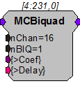
This component is a multi-channel version of the Biquad component. Coefficients must be supplied via the coefficient pointer (>Coef). The Coefficient buffer is [ nBIQ *5] in length and is kept in PM. A delay line of length [(( nBIQ *4)+1)* nChans ] is held in DM.
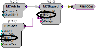
Coefficients can be generated using one of the Coefficient Generator components or supplied via parameter tag (for example, when generated using the Biquad Coefficient Control in OpenController software). One to 16 biquad stages can be specified (nBIQ). The number of stages specified in MCBiquad must match the number of stages specified in the coefficient generator. A separate coefficient generator must be used for each MCBiquad.
Also see Working with Multi-Channel Components.
Note
This component is for use with only high performance processor devices, such as RXn or RZn.
MCFIR
Description:
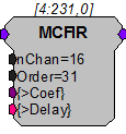
The MCFIR filters each channel of a multi-channel input with an Nth order FIR. Order must be specified as at least 1 and must always be odd. The Coefficient buffer is [Order+1] in length and is kept in PM. A delay line of length [(( Order +1)* nChan )+ nChan ] is held in DM.
The MCFIR component is similar to the MCBiquad filter in that all channels are filtered with the same set of coefficients.
See MCFIR2, if you need to have a different filter for each channel.
Note
This component is for use with only high performance processor devices, such as RXn or RZn.
Equation:
FoN = FIR(FiN)
MCFIR2
Description:
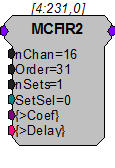
The MCFIR2 is a multi-channel version of the FIR2 component. This component supports a different filter for each channel and multiple coefficient sets.
This component filters each channel in a multi-channel input with an Nth order FIR. Order must be specified as at least 3 and must be odd (nTaps will be even). The Coefficient buffer is [( Order +1)* nChan * nSets ] in length and is kept in PM. A delay line of length [(( Order +1)* nChan )+ nChan ] is held in DM. MCFIR2 supports instant coefficient switching through SetSel . See FIR2, for more details.
Note
This component is for use with only high performance processor devices, such as RXn or RZn.
Equation:
FoN = FIR(FiN)
Ordering:
Odd and even channel coefficients must be shuffled as follows:
n = nTaps = Order + 1
c = nChans
B01, B02, B11, B12, ..., Bn-11, Bn-12 : B03, B04, B13, B14 ...
For Example:
Order = 3
nChan = 6
Filter coefficients in logical order:
These coefficients must be shuffled as follows:
The coefficients are then concatenated and loaded as a row vector as follows (multiple sets are appended):
Coef = [Ch1_2, Ch3_4, Ch5_6][next set...]
MCFIR2D
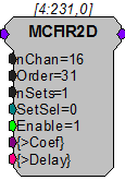
Description:
The MCFIR2D component is identical to MCFIR2, except it has an additional Enable input. The filter is only active when Enable is high. This lets you create a lower frequency FIR filter with fewer taps.
Note
This component is for use with only high performance processor devices, such as RXn or RZn.
MCFIRD
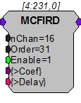
Description:
The MCFIRD component is identical to MCFIR, except it has an additional Enable input. The filter is only active when Enable is high. This lets you create a lower frequency FIR filter with fewer taps.
Note
This component is for use with only high performance processor devices, such as RXn or RZn.
MCSmooth
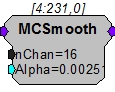
Description:
The MCSmooth is a multi-channel version of the Smooth component. This component however, smooths multi-channel data using an exponential moving average.
Note
This component is for use with only high performance processor devices, such as RXn or RZn.
Equation:
Notes:
FoN = Alpha * FiN + (1 - Alpha) * FoN-1
Larger values of Alpha have less of a smoothing effect and place more weight on recent changes to the input. Smaller values of Alpha respond less to recent changes and produce a greater smoothing effect.
Example:
This example filters out any DC bias effectively AC coupling the multi-channel input signal. MCSmooth is acting as a 9.8 Hz low pass filter. This low passed signal is subtracted from the input signal, so the final output is effectively acting as a 9.8 Hz high pass filter.
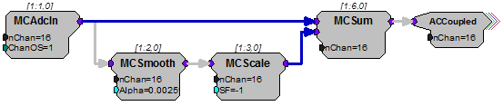
MCSmooth is used to eliminate frequency content above a certain frequency. The equation to calculate Alpha is based on the desired cutoff frequency and the sampling rate of the RPvdsEx circuit.
The equation is:
Alpha = 1 - e(-2*pi*low_pass_frequency/sampling_rate)
where low_pass_frequency is the desired low-pass frequency
and sampling_rate is the sampling rate of the RPvdsEx circuit (e.g. 24414.0625)
In this example, Alpha = 0.00251 corresponds to a ~9.8 Hz frequency cutoff.
Smooth
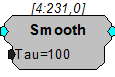
Description:
This component filters with a simple averaging filter.
Equation:
Fo = (1-K) * Fi + K * Fo-1
Where: K = e(-2*pi/(SAMPRATE*Tau/1000))
Example:
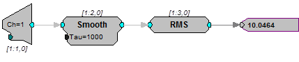
Smooth - This simple example demonstrates how smooth can be used to build an RMS measurement circuit. The input signal is smoothed with a time constant of 1000 milliseconds before the RMS of the input is output.
StereoFIR2
Description:
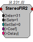
The StereoFIR2 is an optimized stereo FIR filter that supports multiple filter coefficient sets and instantaneous set selection.
This component filters the stereo input with an Nth order FIR. Order must be specified as at least 5 and always odd (nTaps will be even). The Coefficient buffer is [( Order +1)* nSets *2] in length and is kept in PM. A delay line of length [( Order +1)*2] is held in DM.
StereoFIR2 works similarly to FIR2. See this component's description for more information on coefficient set selection.
Note
This component is for use with only high performance processor devices, such as RXn or RZn.
Equation:
FoN = FIR(FiN)
Coefficient Ordering:
The coefficients must be shuffled into stereo sets as follows:
n = nTaps = Order + 1
BL0, BR0, BL1, BR1, ..., BLn-1, BRn-1
For Example:
Order = 5
nSets = 1
Filter coefficients in logical order:
The coefficients must be shuffled and loaded as follows:
Multiple sets are appended logically as illustrated in FIR2.