Time Saving RPvdsEx Techniques
Changing Component Names Systematically
The Change Component Name dialog is accessed via the Edit|Find and Replace menu or the  button on the main toolbar. It can be used to replace all or part of the component name(s) systematically within a selection, sheet, or entire circuit.
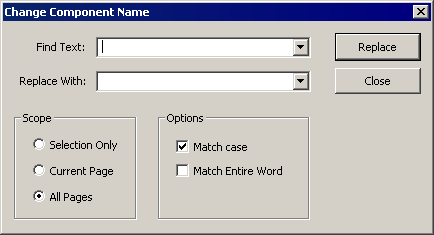
Find Text: Type the text to be changed.
Replace With: Type the desired text.
Scope: Choose to apply the change to a selected section of a circuit, all components and macros on the current sheet, or the entire circuit. To use Selection Only, select the desired area of the circuit before opening the dialog box.
Options: Choose options such as Match case and Match entire word to ensure only the desired component names are changed.
Replace: Click to apply the change. A message box will open and report the number of instances changed.
Close: Click to close the dialog box without applying further changes.
Changing Parameters Systematically
The Change Parameter dialog is accessed via the Edit|Find and Replace menu or the  button on the main toolbar. It can be used to replace parameter values systematically within a selection, sheet, or entire circuit.
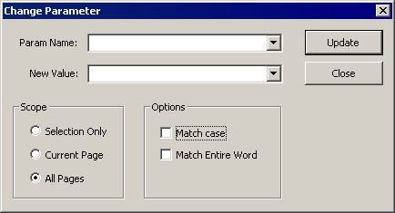
Param Name: Type the name of the parameter to be changed.
New Value: Type the desired value.
Scope: Choose to apply the change to a selected section of a circuit, all components and macros on the current sheet, or the entire circuit. To use Selection Only, select the desired area of the circuit before opening the dialog box.
Options: Choose options such as Match case and Match entire word to ensure only the desired parameters are changed.
Update: Click to apply the change. A message box will open and report the number of instances changed.
Close: Click to close the dialog box without applying further changes.
Using Indexing
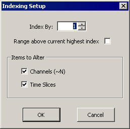
The Indexing Setup dialog is accessed from the Edit menu. It can be used to increment channel number parameter tags and/or time slices for selected components.
Index By: determines the number that Items to Alter will be incremented by. Each selected component will be incremented by the value set here.
Range above current highest index: When this check box is selected the Items to Alter will be set to a number equal to the highest index value present in the document plus the Index By value.
Channels (~N) check box: Select to apply the setting in this dialog box to selected channel number parameter tags, which follow the form: iChan~1.
Time Slices check box: Select to apply the settings in this dialog box to selected components that are currently in a time slice (that is, time slice not equal to 0).
To use indexing:
Select the components to be incremented.
Click the Edit menu and click Index .
Select the desired combination of settings in the Indexing Setup dialog box.
Click OK .
The settings are applied to the selected components.
Selecting Multiple Components
In the example below, an entire circuit construct has been selected. Settings in the Indexing Setup dialog box would be applied to all components.
For example:
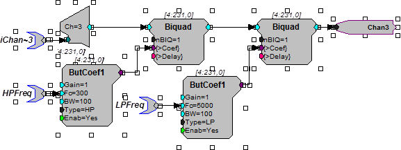
If the Channels (~N) check box is selected, the Time Slices check box is cleared, and the Index By value is set to 1; then iChan~3 would be incremented to yield iChan~4. This would be the only change.
If the Channels (~N) check box is cleared, the Time Slices check box is selected, and the Index By value is set to 1; then the ButCoef components currently set to time slices 5 and 6 would be moved to time slices 6 and 7 respectively. No other components would be affected.
Using the Preferences Dialog Box
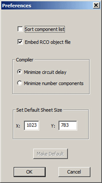
The Preferences dialog is accessed from the Edit menu. It can be used to set compiler and control object file settings.
Sort Component List: When checked, the components in each group will be arranged in alphabetical order when viewing the component selection browser.
Embed RCO Object File: If this option is checked, the RPvdsEx file will be saved with the extension rcx. Files with this extension contain both the graphical circuit representation for use within RPvdsEx and the control object information to be loaded to a device. This eliminates the need for a separate rco file.
Note
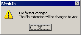
The Build RCO button on the Implement toolbar is grayed out when the check box is selected. If a circuit is saved after this preference has been modified, RPvdsEx will display the following message to alert the user that the file extension has been changed:
Compiler: Set the compiler to minimize the circuit delay or the number of components.
Set Default Sheet Size: Type new values in the X and Y boxes to set a sheet size for all new sheets.
Make Default: To save preferences for future RPvdsEx sessions, click Make Default and click OK .
Updating Number of Channels Systematically
The Update Number of Channels dialog is accessed via the Edit|Find and Replace menu or the  button on the main toolbar. It can be used to replace channel number parameters systematically within a selection, sheet, or entire circuit. The change is implemented for both component parameters and macro parameters and provides an easy way to avoid channel number mismatches.
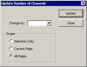
Change to: Type the desired number of channels.
Scope: Choose to apply the change to a selected section of a circuit, all components and macros on the current sheet, or the entire circuit. To use Selection Only, select the desired area of the circuit before opening the dialog box.
Update: Click to apply the change. A message box will open and report the number of instances changed.
Close: Click to close the dialog box without applying further changes.
RPvdsEx Shortcuts
Placing Links
- Press the Spacebar to activate single-click placing of a link.
Or - Double-click the output terminal where you want to start a link.
Cancel Linking
- Right-clicking the workspace will cancel the link option.
Keyboard Shortcuts
Most standard Windows keyboard shortcuts (such as Ctrl + c to copy a selected item) can be used in RPvdsEx.
Copying Circuits
In cases where you want to repeat a circuit several times, select the block by clicking and dragging a box around the items you want to select. Then choose copy and paste to create a second copy of the circuit.
Using Cut, Copy, and Paste
Cut, Copy, and Paste can speed up circuit design. They affect the currently selected items within the RPvdsEx circuit diagram. A single component or an entire circuit can be cut, copied, or pasted. Items that are selected are surrounded by small square selection handles. To select multiple items, hold down Shift and click each item to select or click and drag a box around all the items to select.
For example:
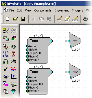
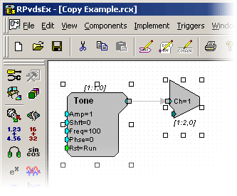
Starting with a circuit that plays a tone out of channel 1, we copy and paste the circuit to create another tone that plays out of channel 2.
Select the circuit by clicking and dragging a box around the entire circuit. Items that are selected will have square selection handles around them.
On the Edit menu, click Copy .
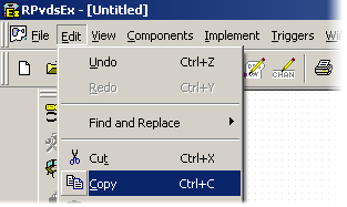
On the Edit menu, click Paste to paste a copy of the circuit.
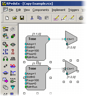
Change the second DAC output to channel 2 , and set the tone to the desired frequency and amplitude .