Input/Output
Input and Output components handle input and output for circuits. Inputs include A/D converters, TTL inputs, and Trigger inputs. Outputs include D/A converters and TTL outputs. Use circuit components from this group to connect a circuit to the physical world.
This group includes the following components:
This group also includes the following components, if RPvdsEx Device Setup is configured for a high performance device, such as the RXn or RZn:
AdcIn
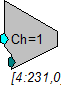
Description:
Feeds the signal stream with A/D input channel specified. Converts 24 bit integer input to floating point value. Also scaled and shifted to yield calibrated voltage level.
A parameter input allows users to dynamically change the channel number.
Equation:
Fo = ADC channel D1
Example(s):
Scale and Add, Scale and Add.
Butterworth Coefficients, ButCoef.
BitIn
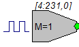
Description:
Feeds the signal chain with bit(s) from the digital input port. BitIn will logic 'OR' all bits of the input port specified in Mask to produce a single logic high or low.
Standard integer values for addressing digital bits are provided in the table below.
Note
There is a two cycle delay when using the BitIn component.
Equation:
Lo = If (Digital Input Port && D1)
Example(s):
If Digital Input Port = 7 and D1 = 3 Then Lo = 1
If Digital Input Port = 8 and D1 = 3 Then Lo = 0
BitOut
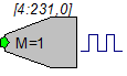
Description:
Sets or clears bits of the digital output port based on the input's logic level. All bits specified in Mask will be set when the input is high else the bits will be cleared.
Standard integer values for addressing digital bits are provided in the table below.
Note
There is a three cycle delay when using the BitOut component.
Important
In circuits that contain both BitOut and WordOut, the Bitmasks cannot overlap. For example, in a circuit where the BitOut and WordOut both use bit 2 (BitMask=4), the circuit will set the value based on the last component in the circuit.
Equation:
Digital Output Port = Li masked by D1
Example(s):
If Li = 1 and D1 = 3 then Digital Output Port bits 0 and 1 = 1
If Li = 0 and D1 = 3 then Digital Output Port bits 0 and 1 = 0
DacOut
Description:
Converts floating point signal input to integer value and sends to specified D/A output channel. The value is scaled and shifted to provide calibrated voltage output.
A parameter feed allows users to change the channel output dynamically.
Equation:
DAC channel D1 = Fi
Example(s):
See ScaleAdd.
MCAdcIn
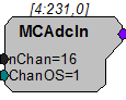
Description:
This component is a multi-channel version of the AdcIn component. MCAdcIn feeds the circuit with the multi-channel input from a high performance device, such as the RX5. With the RX5, analog signals are digitized on a preamplifier and sent to the base station via its fiber optic ports (Amp-A, Amp-B, Amp-C, and Amp-D). The channel offset (ChanOS) can be used to specify acquisition channels, such as channels from a specific amplifier. For example, to acquire signal data from Amp-B you would set the channel offset to 17. The number of channels fed to the multi-channel output is specified by nChan.
The minimum and maximum number of channels allowed in multi-channel signals is 4 and 256, respectively. However, the user must consider their hardware configuration when setting the number of channels. For example, the maximum number of analog input channels available on the Pentusa (RX5BA-5) is 64. Therefore, the number of channels for the MCAdcIn component must not exceed 64 when using this device.
Also see Working with Multi-Channel Components.
Note
This component is for use with only high performance processor devices, such as RXn or RZn. See the reference section for your device in the System 3 Manual for more information.
MCDacOut
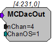
Description:
This component is a multi-channel version of the DacOut component. MCDacOut converts the floating-point values in the multi-channel input signal to integer values and sends them to the specified analog output channels. The values are scaled and shifted to provide calibrated voltage output.
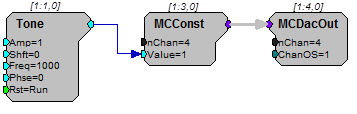
The minimum and maximum number of channels allowed in multi-channel signals is 4 and 256, respectively. However, the user must consider their hardware configuration when setting the number of channels. For example, the maximum number of analog outputs available on the Pentusa is four. Therefore, the number of channels for the MCDacOut must not exceed four.
Note
This component is for use with only high performance processor devices, such as RXn or RZn.
MCeStim
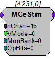
Description:
This component is used to send digital stimulus waveforms to the IZ2 Stimulus Isolator. The total number of channels configured for stimulation is defined in the nChan parameter. A multi-channel input accepts stimulus waveforms and an eight-channel output returns the actual stimulus voltage for monitoring. The MonBank parameter selects which bank of eight channels to be monitored.
The logic input parameter VMode determines if the IZ2 acts as a constant current (0) or voltage (1) source.
Use of the IZ2_Control macro is highly recommended as it provides all of the necessary settings for the IZ2 Stimulator.
Note
This component is for use with the IZ2 Stimulus Isolator and RZ2 high performance processor devices. See the System 3 Manual for more information.
StereoAdc
Description:
Generates stereo signal from channel 1 (left) and 2 (right) ADC inputs.
StereoDac
Description:
Plays stereo input out of channel 1 (left) and 2 (right) DAC outputs.
TimeStamp
Description:
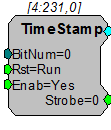
TimeStamp is used with the Barracuda (RV8) and Multifunction Processor (RX6). It is a submicrosecond accurate event-timer. On each tick of the sample clock the TimeStamp waits for a trigger input. When the trigger goes high, the TimeStamp component outputs a value equal to the number of microseconds since the start of the sample period.
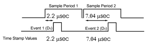
The TimeStamp can detect triggers on a specified digital input line. The BitNum parameter determines which digital input bit is monitored for triggers. A Reset line (Rst) resets the TimeStamp and readies it for the next event. The Enable (Enab) line enables the TimeStamp function (Yes=1 to enable). The Strobe out should be connected to a latch or buffer operation to save the TimeStamp value (see example below).
Note
On the RV8, bits 0-15 can be monitored for triggers. On the RX6, bits 0-3 can be monitored.
TrgIn
Description:
Feeds the signal chain with the specified trigger source. Use to feed system triggers to various Logic inputs of counters etc. Trigger options set before run.
When the zTrigIn component is configured for a software trigger, the trigger will remain high for one sample. However, if the zTrigIn is configured for the zBusA or zBusB trigger the time high will depend upon the sample rate. For example, at 6 kHz the trigger will remain high for one sample, but at 25 kHz the trigger will remain high for 5 samples.
If you wish to use the zBusA or zBusB trigger and need a single sample trigger pulse, use an EdgeDetect component to detect the rising edge of the trigger before feeding the trigger line to enable, reset, or other triggering parameters.
Equation:
L O = If (D1)
Example:
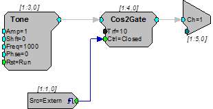
External Trigger - This circuit uses an external trigger as an Enable line to gate a tone on and off. When the external trigger goes high, the Cos2Gate will rise with a 10 ms rise time. When the external trigger goes low, the Cos2Gate will fall with a 10 ms fall time.
WordIn
Description:
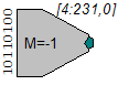
Feeds the chain with an integer representation of the digital input port. The digital input port is logic 'ANDed' with the specified Mask and the resulting value is fed to the signal chain.
Note
There is a two cycle delay when using the WordIn component.
Equation:
Io = Digital Port In 'AND' D1
Example(s):
If Digital Port In = 7 and D1 = 3
Then Io =3
Also see Working with WordIn - WordOut.
WordOut
Description:
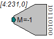
Passes an integer value to the specified bits of the digital output port. Only bits specified in the Mask will be affected on the output port. Bits not specified in the Mask will be unaffected and can be used for other things.
Note
There is a three cycle delay when using the WordOut component.
Important
In circuits that contain both BitOut and WordOut, the Bitmasks cannot overlap. For example, in a circuit where the BitOut and WordOut both use bit 2 (BitMask=4), the circuit will try to set the value based on the last component in the circuit.
Equation:
Digital Port Out = Ii for bits specified in D1
Example(s):
If Ii = 7 and D1 = 3
Then Port Out =3
Also see Working with WordIn - WordOut.
RX Support for I/O Components
The tables below compare high performance processors' support for various analog input/output RPvdsEx components.
Analog Outputs
Analog Inputs
x supported
x* channels 1-16 access optical inputs, channels 128 and 129 access audio inputs
x** component supported for access to optical inputs only (use AdcIn or StereoADC for analog input BNCs)
† The StereoAdc component is limited to ADC channels one and two only.