Delay Functions
Delay Function components can be used to create intentional delays between signals or to synchronize delays that are introduced by the ADC and DAC. See DAC and ADC Delays, for more information.
This group includes the following components:
This group also includes the following components, if RPvdsEx Device Setup is configured for a high performance device, such as the RXn or RZn:
ADCDelay
Description:
Time delay equal to ADC group delay for the RP2.
Note
The ADCDelay component will always delay for 41 samples, which is correct for an RP2. Because of the different ADC delays of the various processors (RP2.1 = 65 samples, RX6 = 70 samples, etc.), this component will delay accurately for the RP2 only.
Equation:
Output = (Input[-ADCDelay])
Example:
Analog-to-Digital Delay
File: Examples\ADCdelayEx.rcx
Default Device: RP2 Processor
Sampling Rate: 50 kHz
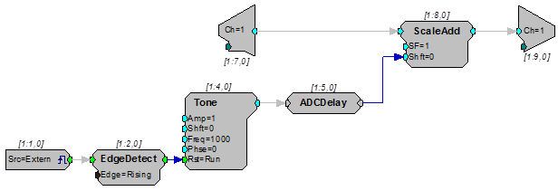
This example mixes the input from channel one with a tone generated by the circuit. The phase of the tone is reset to zero when an external trigger is detected. The ADCDelay component is included in the circuit before the ScaleAdd to ensure that the tone and the input signal phase are matched.
DACDelay
Description:
Time delay equal to 30 samples, the DAC group delay for the RP2 and RP2.1.
Note
The DACDelay component will always delay for 30 samples, which is correct for an RP2 and RP2.1. However, the RA16 has a DAC delay of 18 samples and the RV8 has a DAC delay of 2-4 samples. This component will accurately account for the DAC delay for the RP2 and RP2.1 only.
Equation:
Output = (Input[-DACDelay])
Example:
Digital-to-Analog Delay
File: Examples\DAC_ex.rcx
Default Device: RP2.1 Processor
Sampling Rate: 50 kHz
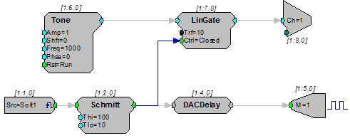
This example plays a tone from analog output channel one when it receives a software trigger. A DACDelay is used to synchronize the output on Bit-1 of the digital output with the output of the Tone on the DAC. A LinGate is used to ramp the tone on and off with a 10 ms rise-fall time. A Schmitt trigger controls the duration of the tone.
Latch
Description:
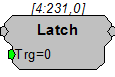
Latches input to output on the rising edge of a trigger. The output will remain unchanged until the trigger goes high again and the output is latched to the new value.
Note
Until the first time the trigger goes high, the output will be zero.
Equation:
If (Trg) then Output = (Input) else Output remains unchanged.
LongDelay
Description:
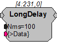
Time delay using SDRAM. (Will not work with RP2-5, because it does not have memory. Can only use short delay). Data port can be used to view data currently in delay line.
Equation:
Output = (Input[-Nms])
Example:
Sum, Sum.
LongDynDel
Description:
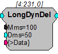
The LongDynDel component performs a dynamic delay using SDRAM. Unlike the LongDelay component, which has a delay value that is fixed at compile time, the delay value (Dms) on LongDynDel is dynamic with a minimum accepted input value of 0.01 milliseconds. The maximum delay value (Mms) is fixed and Dms can never be allowed to exceed it. The LongDynDel component can be used to generate delays that are not quantized to the sample rate. To do this, it cross fades (averages) the two points about the delay. An example is generating Doppler effects for 3D auditory displays.
When setting up a variable delay line, keep in mind that the signal may be distorted if the delays are not multiples of the sample period. When the delay is not a multiple of the sample period, there is a linear relationship between the location of the delay and the amount that the point on either side of the delay contributes to the corresponding point in the delayed signal. For example, if the desired delay was 0.25 samples, each point in the delayed signal would be described by the following:
(1-0.25)*sample value before delay + 0.25*sample value after delay.
Because this component uses cross fading to implement the delay, it is not suitable for delaying a TTL pulse. To delay a TTL pulse, use either the TTLDelay or TTLDelay2 component. Because it uses SDRAM, it will not work on the RP2-5.
Note:
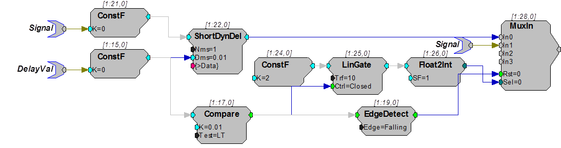
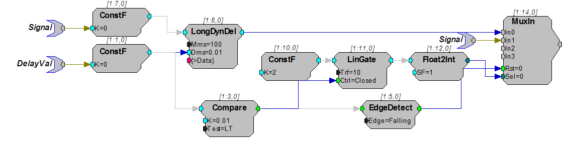
When using Parameter Tags to input the delay value (Dms), input values less than 0.01 ms will generate an error. To dynamically implement "no delay" intervals, use a Compare to bypass the delay during those intervals as shown in the example circuit segment below.
MCDelay
Description:
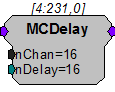
MCDelay implements a delay of n samples on each of the channels in the multi-channel input. This component uses internal device memory. Because internal memory is a limited resource (20kB) you may need to monitor the available internal memory when using this component.
See the FreeDM component. Also see Working with Multi-Channel Components.
Note:
This component is for use with only high performance processor devices, such as RXn or RZn.
MCDelay2
Description:
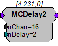
MCDelay2 implements a delay of n samples on each of the channels in the multi-channel input. This component is optimized for short delays only.
Note:
This component is for use with only high performance processor devices, such as RXn or RZn.
MCLatch
Description:
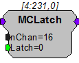
MCLatch is the multi-channel version of the Latch component. It latches input to output on the rising edge of a trigger. The output will remain unchanged until the trigger goes high again and the output is latched to the new value.
Note
Until the first time the trigger goes high, the output will be zero.
Equation:
If (Trg) then Output = (Input) else Output remains unchanged.
MultLatch
Description:
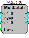
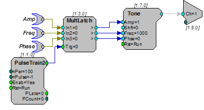
The 'MultLatch' latches multiple inputs to multiple outputs when triggered. Inputs can take all formats including Parameter tags. The Multlatch should be used when several parameters need to be sent out at the same time. In the example below the frequency, amplitude and phase of a tone generator are latched at the same time.
Tech Notes
All inputs and outputs act as Parameters.
Equation:
If (Trg) then Output = (Input) else Output=0
Example:
MultLatch - In this example, a PulseTrain2 triggers the MultLatch. Any changes in the ParTags will modify the phase, frequency and/or amplitude of the Tone generator.
SampDelay
Description:
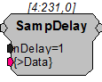
Time delay using SDRAM. (Will not work with RP2-5 because it does not have extended memory). This component is similar to the LongDelay component except the delay parameter nDelay is specified in samples instead of milliseconds. Data port can be used to view data currently in delay line.
ShortDelay
Description:
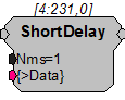
Time delay using internal memory. Maximum delay of 10 ms. Data port can be used to view data currently in delay line.
Note that there are only 1024 32-bit words of Dynamic Memory allocated for Delay functions. The number of short delays that are allowed is dependent on the delay length and the sampling rate. For example a millisecond ShortDelay consumes 50 words at 50 kHz sampling rate.
Equation:
Output = (Input[-Nms])
Example:
Short Delay, ShortDelay.
ShortDynDel
Description:
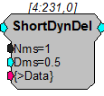
The ShortDynDel component implements a dynamic delay using internal memory. Unlike the ShortDelay component, which has a delay value that is fixed at compile time, the delay value (Dms) on ShortDynDel is dynamic with a minimum accepted input value of 0.01 milliseconds. The maximum delay value (Mms) is fixed and Dms can never be allowed to exceed it. The maximum value of Mms is 10 milliseconds. If a longer delay is required, use the LongDynDel component, which has a larger memory buffer. This component can be used to generate delays that are not quantized to the sample rate. To do this, it cross fades (averages) the two points about the delay.
When setting up a variable delay line, keep in mind that the signal may be distorted if the delays are not multiples of the sample period. When the delay is not a multiple of the sample period, there is a linear relationship between the location of the delay and the amount that the point on either side of the delay contributes to the corresponding point in the delayed signal. For example, if the desired delay was 0.25 samples, each point in the delayed signal would be described by the following:
(1-0.25)*sample value before delay + 0.25*sample value after delay.
Because this component uses cross fading to implement the delay, it will not work correctly for delaying a TTL pulse. To delay a TTL pulse, use either the TTLDelay or TTLDelay2 component. Because it uses internal memory, it is compatible with the RP2-5.
Note
When using Parameter Tags to input the delay value (Dms), input values less than 0.01 ms will generate an error. To dynamically implement "no delay" intervals, use a Compare to bypass the delay during those intervals as shown in the example circuit segment below.