Helpers
Helper components are used to simplify circuit design (HopFrom, HopTo), debug a circuit (Graph, ParWatch), control a circuit while it is running (DataTable), or send data between the PC and the RPX (ParTag, Graph, DataFile).
Note to RL2Stingray users: Remember to turn off Helpers before undocking the Stingray.
This group includes the following components:
DataTable
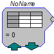
Description:
The DataTable can be used to supply data to a parameter or Data type input. Supports output of scalar values; Biquad, IIR, and FIR filter coefficients; and State Machine values. The up and down arrows manually change the index that selects the output data and are accessible using ActiveX controls or in RPvdsEx. Table values are set before the chain is run.
To open the Quick Data dialog box, double-click the DataTable icon.
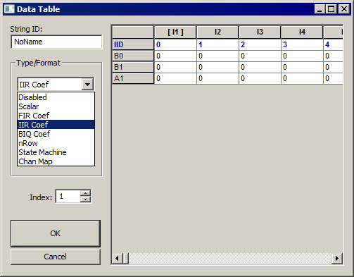
The DataTable dialog box has a drop down menu for the format of the Table. The possible formats are:
For most of the DataTable types a row index is generated for the number of rows required in the data table. Each table can hold 1024 values. The values can be divided between the number of rows and columns. For example a Table with 700 rows would have 1 column. While a table with 20 rows could have 51 columns. The number of rows is controlled by a number box like the one below.
You select the Type/Format of the DataTable and the No. Rows or Coefficients in the table and then reformat the table.
Changing the output of a Data Table
To change the Column number while the circuit is running click on the up/down arrows on the DataTable icon from within RPvdsEx.
The index of the Data Table can also be changed using an ActiveX control.
Example(s):
FIR/Data Table, FIR.
DestinFile
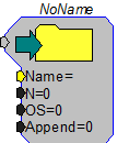
Description:
A DestinFile can transfer data from the RP Device to the PC. DestinFiles are supported within RPvdsEx only. While designing the circuit, information like the exact location of the file for storing the data (NAME), the number of data points to be stored in the file (N), and the offset value for the data file (OS) are set in the component.
If number of data points to be stored is not known, '0' can be entered. To append the data to an existing data file 'Append' should be set to '1'.
The Data transfer is initiated by clicking the green arrow in the DestinFile component.
The DestinFile component can also be used with 16-Bit integer format ('. I16') data if the 'Comp to 16' component is used to convert the data to 16-Bit integer format before transferring it to the destination file. Data cannot be saved to a 'wav' file using the DestinFile component.
Note
The save button for the DestinFile initiates a save for all components that share the name of the specified DestinFile. If two components have the same name, the button will save both simultaneously. To ensure only the intended component is saved, give each DestinFile a unique name.
Example:
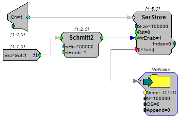
DestinFile - The example below collects 100000 points from an Analog channel input when a software trigger is set. After the data is acquired the user can download the signal information by clicking on the green arrow.
Graph
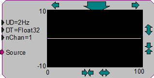
Description:
Graph contents of buffer connected to Source. Graph works within RPvdsEx. The arrows surrounding the graph are used to change the scale of the x and y axes. The large arrow is used to manually update the graph. Double click to modify update mode with one of the listed options.
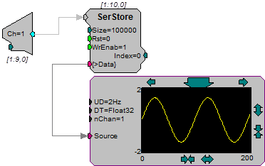
Notice that the connector points to the Graph.
Graph can graph all data types, as well as multiple channels. With a high speed USB connection it is possible for graph to refresh the screen 10 times a second.
HopFrom
HopTo

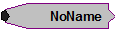
Description:
Allows graphical breaks in the RPvdsEx circuit, which allows one to build complex circuits without overlapping lines. Used as a pair with one HopFrom and one or more HopTo. There are no accessible parameters. Double-click on Hop to access the label.
Example:
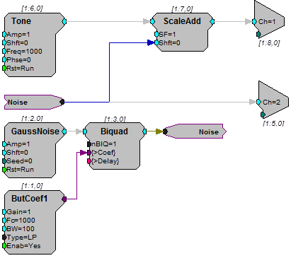
Hops
In this example a HopTo is connected to the output of the Biquad filter, and named 'Noise'. A separate HopFrom named 'Noise' is connected to a ScaleAdd component and to a second DAC.
Iterate
Description:
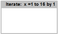
An iteration box is a helper that greatly simplifies multi-channel circuit design. The sub-circuit within the iterate box is duplicated a specified number of times. The number of duplications is specified using the variable parameter x along with its start and step size. Adding the character 'x' enclosed in braces ({x}) in the sub-circuit will cause consecutive values from 1 to x to be inserted in place of the 'x' in each duplicate.
For example:
If x = 16, start = 1 and step = 2, then there will be eight iterations and x will take the values 1, 3, 5, 7,.., 13, and 15.
Using Iteration
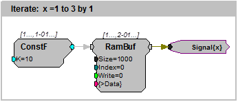
An Equivalent Circuit Without Iteration
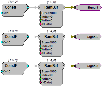
Using iterations greatly simplifies circuit design. However, it does not reduce the number of components. The number of components created by the circuits above is identical.
In fact the circuits are equivalent and produce identical results when compiled.
The main advantage of using iterations is the manageability of the circuit. It makes the circuit concise and easy to manage and edit. Each modification in the circuit needs to be made only once.
When the iterate component is added, the user can drag the box boundaries around any sub-circuit. All components and links must be either inside or outside the box. Intersecting the box with a link is not permitted.
Note
When hops or parameter tags are used within the iterate box, they should typically include the variable {x} in their labels. If the x variable is not used, a single object such as a parameter tag will have multiple sources.
Using Variables
Iterations can make use of up to three variables, including the x variable and two constants, a and b. The variables can be accessed and edited in the parameter box which can be opened by double-clicking the top border of the iterate box. The variables may be used in the labels of hops, parameter tags, or component parameters.
Adding the character for any of the variables (x, a, or b) within braces (such as, {a}, {b}, or {x}), will cause the value for the variable to be inserted in place of the symbol in every iteration. With the variable x, such as {x+a}, the value of x is incremented with each iteration. This is very useful when a channel offset number is needed.
For example:
If x = 16, start = 1, step = 1, and a = 16, then (x+a) will take values 17, 18, 19,..., 31 and 32.
Using Iterations with MCToSing
Another powerful and efficient use of the iterate component is its use with the multi-channel component MCToSing. Together these components can be used to extract single-channel signals from a multi-channel signal. Each channel can then be processed by single channel components. Ordinarily, a separate circuit segment would be required to extract and process each signal. With the use of iterate, the user can put the circuit for a single channel within the iterate box, and then put {x} in the channel selector of MCToSing and in the labels of any parameter tags in the sub-circuit.
Assigning an Iterate Box to More Than One Processor
Assigning a sheet that contains an iteration box to multiple processors allows the user to build the iterate box with the associated circuitry within it, just once. When this technique is used, the character d, within braces ({d}), must be added in the circuit wherever the iterate box needs to be different for each processor. The letter d will take the value corresponding to the processor to which it is assigned. Values are 0, 1, 2, 3 and 4 for the main and auxiliary processors respectively.
For example:
If x = 16, start = 1, step = 1, a = 16, then {x + (d*a)} will take values:
1, 2, 3,..., 15, 16 in the first auxiliary processor
17, 18, 19,...,31, 32 in the second auxiliary processor
33, 34, 35,..., 47, 48 in the third auxiliary processor
49, 50, 51,..., 63, 64 in the fourth auxiliary processor
Note
In this example, the four auxiliary processors are used to process 16 channels each.
Because the value associated with the main processor is 0, the formula used in this example should not be used when the iteration box is assigned to multiple processors.
The Duplication Information Dialog Box
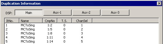
After the circuit has been compiled a Duplication Information Dialog Box can be displayed by right-clicking a component and clicking Duplication Info. The Duplication Information dialog box displays several columns of information regarding the state of the component and its parameters in each iteration of the circuit. Buttons at the top of the dialog box allow the user to display information for each processor to which the component might have been assigned.
The first four columns are always the duplication number (ItNo.), component name (Name), component number (CmpNo.), and time slice (T.S.). The component numbers displayed are offset for each auxiliary processor. Because each processor can utilize up to 256 components, each processor is offset by a multiple of 256. For example, the main processor uses component numbers 1-256, while the Aux-1 processor uses component numbers 257-512.
The standard columns are followed by columns for each of the component's parameters. This list of iterations and variable values are for user reference and debugging.
For example, the duplication information for the MCToSing component from the example below is shown here. Notice that the channel number (ChanSel) varies from 1 through 16. In the example the iteration variable {x} was assigned to channel number.
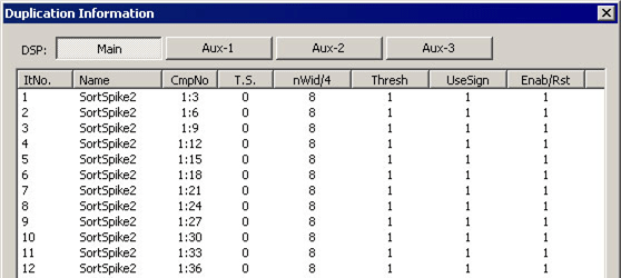
Similarly, the duplication information for the SortSpike2 component from the example below is shown here. Because the variable {x} is not a part of any of the parameters of the SortSpike2 component, none of the columns have a list of successive or changing values.
Example:
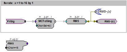
Iterations are commonly used with a MCToSing and single channel processing components, to extract and process each channel of a multi-channel signal. When MCToSing is used inside an iteration box, the variable x associated with the iteration box can be assigned as the channel number. In the example below, FiltSig is a 16 channel signal, from which each channel is extracted and the RMS value is calculated. This entire circuit is being iterated 16 times, that is, when the circuit is compiled the iterated portion of the circuit will be duplicated 16 times. Each instance will process a different channel. Notice that the variable x is included everywhere in the circuit where distinctions need to be made between the channels (for example, parameter tags). The output RMS signal is available as a new MC signal using the MCFromHop component.
MemoBox
Description:
A MemoBox component is used to place text in the circuit. The MemoBox does not affect the functionality of the circuit in any way. It is useful for describing how the circuit works (similar to comments in source code) and labeling parts of the circuit.
ParTag
Description:
Parameter tags are used to control component Parameter variables and access data from signal outputs, component parameters and data ports from a program while the chain is running. To find out how parameter tags are used in programming see the ActiveX Manual.
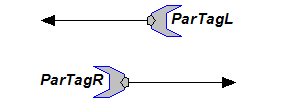
Parameter tags always point to the parameter component.
ParTagL and ParTagR function the same. The difference is for aesthetic purposes.
The maximum length of a parameter tag's name is 32 characters. Parameter tag names are case sensitive.
Parameter tags function in Control Object Files (*.rco) that are accessed via ActiveX controls or through DLLs.
Connecting to a Signal Input
Parameter tags cannot access signal inputs directly. Signal Inputs are found in the top right-hand part of the components. The illustration below shows two correct parameter connections and an incorrect one (red connection path).
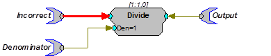
To access a signal input use one of the following: ConstF, ConstI or ConstL. The example below uses a constant Float to convert the parameter tag into signal output that can be fed into a signal input.

ParWatch
Description:
Parameter Watch. When connected to the output of any component, it reports the value of the component. Very useful for debugging circuits and checking cycle usage. The default data type for ParWatch is floating point.
When connected to a parameter value that allows any type a floating point value will be returned. This gives erroneous values for integer or logical values. To fix this include an INT2FLT or TTL2FLT component between the output and the ParWatch.
Monitoring Output Values
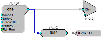
This example shows how a parameter watch can be used to monitor the levels of another component. Here it is reporting the RMS value.
ScriptTag
Description:
A ScriptTag makes it possible to include scripting in RPvdsEx circuits. This powerful new feature allows for complex automatic access to circuit elements via an embedded basic language. It includes an editor and a debugger and has been extended to include a number of powerful hardware access commands.
The code within the scripted tag is executed when the tag is accessed (read from or written to). This is done in the same manner as accessing parameter tags with ActiveX commands or through OpenEx.
Important
This component is primarily for TDT use. Comprehensive documentation and support for end-user scripting is not available at this time.
Example:
This example sets the value of a ScriptTag named HPFreq with ActiveX commands.
setval = RP.SetTagVal(HPFreq,hp)
When the ScriptTag is written to, the internal code is run. The internal code may or may not use the value 'hp' from the SetTagVal command. Therefore, if you only need to trigger the code to run, the value for 'hp' is irrelevant.
Note
A ScriptTag given the reserved name 'InitScript' will execute its code when the RPvdsEx circuit is run. This enables the user to set default values without having to explicitly access the ScriptTag.
SourceFile
Description:
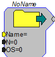
A data file sends a file from the PC to the RP device. SourceFiles are supported within the RPvdsEx application and with ActiveX controls. During the design of the circuit using a SourceFile, the number of points to load from the file and the OS (offset of the data file) are set. Once the circuit is running, the information from the data file resides in a memory Buffer.
The data file can have any of the following data formats 32-Bit float, 32 and 16-bit integer, ASCII, or WAV files. If using ASCII format, the file should contain a column of numbers, one per line.
The memory buffer of the component that the SourceFile is connected to has access to the file. In most cases a portion of the file is stored in a memory buffer. The size of the buffer is dependent on the amount of memory allocated to the serial or RAM buffer.
When a SourceFile is used with a serial or RAM buffer the write enable line must be set to 0 (read from buffer).
When used within RPvdsEx, before the chain is run the user must define the file name, number of points to read, and offset. With ActiveX it is possible to control some of these variables dynamically.
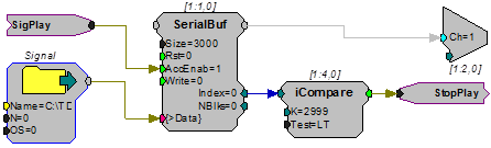
In the example above, when the circuit starts the SourceFile is loaded and the serial buffer plays the signal until it reaches the end of the buffer. The iCompare sends out a logical high while the buffer index is less than 2999 (buffers start at zero) when it reaches 2999 StopPlay is set to 1.
Example(s):
3D Circle, Reverb.