The Test Equipment
The care used in setting up your test area must also be taken when selecting and setting up your test equipment. TDT's ABR system is part of a modular experiment platform. Each module in the system is designed for exceptional signal fidelity, precise timing, low noise, and ease of use.
The sub-sections below discuss the role each part of the system plays in running an ABR experiment and provides information on making the necessary connections.
Needle Electrodes
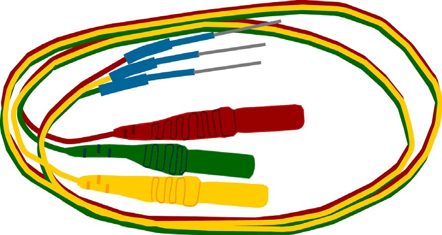
In a research environment with non-human subjects, ABRs are typically recorded using sub-dermal needle electrodes. There are a wide variety of suitable electrodes available. When working with a TDT System, you will need electrodes with 1.5 mm female safety connectors (also known as Touch-Proof connectors) to be used with the Medusa4Z. TDT recommends disposable, 12 mm long, 27 gauge needle electrodes with 18" color coded lead wires. In general, selecting the shortest available lead wires helps keep the noise floor as low as possible. Some test protocols using small subjects, such as mice, may find that 29 gauge electrodes are more workable. Keep in mind that smaller gauge electrodes are lighter, but are also less robust and more likely to dull quickly.
Medusa4Z BioAmp
Biological signals from the subject are input to the Medusa4Z for amplification and digitization. The Medusa4Z transfers digitized data to the RZ6 processor via a fiber optic cable. The fiber optic connection electrically isolates the Medusa4Z from the RZ6 and ensures that no additional noise is introduced to the biologic signal. This design is intended to be used with the preamplifier running on battery power alone, placed inside the Faraday cage with only the fiber optic cable connecting it to the RZ6.
Max Input: ±10 mV max input.
Gain: The Medusa4Z amplifies the signal by 100x before digitizing and transferring it to the RZ6. The RZ6 automatically accounts for this 100x gain when receiving the data, yielding a net unity gain.
Power: The Medusa4Z is powered by a Lithium-ion battery. It can be charged in 4-6 hours and will power the amplifier for up to 30+ hours when using a single active channel.
Important
The supplied battery charger must NOT be connected or inside the enclosure when running experiments. To protect the battery, do not leave the Medusa4Z on the charger for an extended period of time (1+ week).
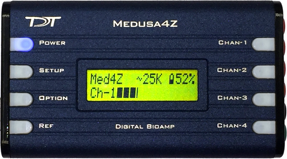
By default the Medusa4Z will boot up as shown above. A few changes must be made to the default settings to use for ABRs.
Caution
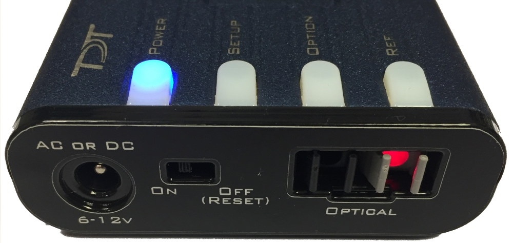
Use the POWER button on the top of the Medusa4Z to turn it on and off. There is an ON/OFF (RESET) switch on the side which completely disconnects the battery and loses all user settings. You should only use the ON/OFF (RESET) switch if storing the Medusa4Z for an extended period of time.
For more information on the Medusa4Z and full system specs, see the System 3 Manual.
Speakers
TDT's MF1 Multi-Field Magnetic Speaker is suitable for testing the hearing range of mice, rats, and guinea pigs. It can be configured for either free- or closed- field use. See Configuring the MF1 for Closed Field Operation. It has a built-in 8-32 threaded hole for use with standard laboratory mounting hardware. Aluminum mount/base fittings are included for easier positioning.
For Open Field experiments, place the speaker 10 cm from the subject. Be sure to position it to the side of the subject, in line with the ear, NOT in front of the subject.
For more information on the MF1 speakers and full system specs, see the System 3 Manual.
Closed Field Setup
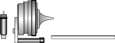
Each MF1 comes with a tapered tip for Closed Field experiments. The tip mates with the provided ⅛" outside diameter (O.D.) PVC tubing (10 cm included). The MF1 comes with an inline filter (pictured at left) that connects between the RCA cable and speaker input. This filter should always be in place when using the MF1 speakers in closed-field mode. In closed-field mode, the MF1 has undesirably high low frequency output. This filter reduces the speaker output at low frequencies so that the output range can be equalized. When using the tube tip, use the MF1's inline filter and the shortest tube possible. You can cut the 10 cm tube to the desired length. A 3 - 5 cm tube length is typical. The tube should slide snugly into the tube tip. You can push firmly without fear of damaging the tube. If you have trouble inserting the tube, a small amount of silicon spray can be used. It may be easiest to spray silicone lightly on a cloth first then put the tip of the tube on the cloth to apply it.
Warning
Other lubricants (WD-40, grease sprays, or similar) should not be used as they can damage the O-rings surrounding the tube tip, or the tubes themselves.
RZ6 Signal Processor
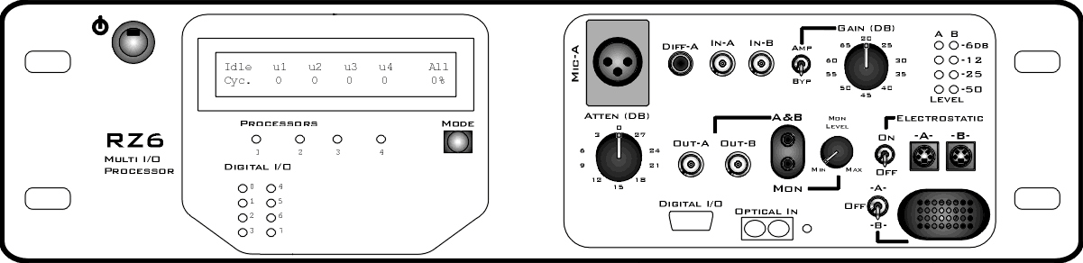
The RZ6-A-P1 Multi I/O Processor provides the processing power for averaging signal inputs and the digital-to-analog converters and amplifiers for producing the stimuli. It also provides the precise timing essential to evoked response experiments.
The power input and optical connection to the PC are located on the back. The input/output support (such as speaker drivers) and attenuation that is incorporated into the device are all accessed on the front panel.
Stimulus Output The RZ6's can generate a stimulus in the frequency range of DC - 88 kHz and is well suited for standard ABR testing.
A built-in stereo power amplifier drives the stimulus signals through TDT's MF1 multi-function speaker via the BNC labeled Out-A.
Use the RCA cable and BNC to RCA adapter (included with the MF1 kit) to connect OUT-A to the RCA connector on the speaker.
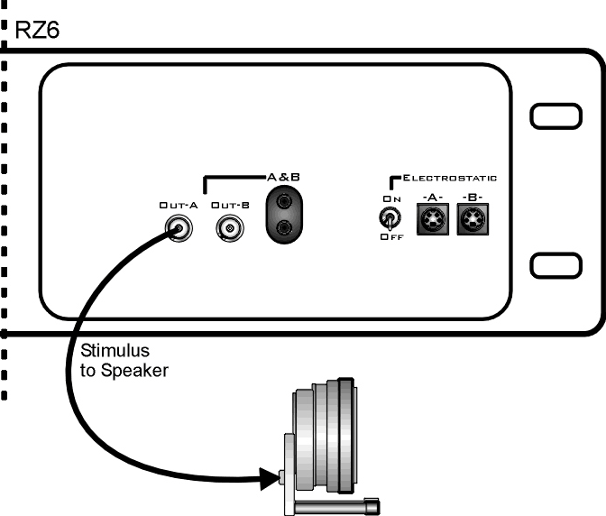
Important
When using the MF1, the ON/OFF switch next to the outputs marked Electrostatic must be in the OFF position to reduce noise.
Attenuation Typically, stimulus attenuation is handled via software. The Atten knob on the front panel provides optional manual attenuation applied to the signal before it is output. This can be useful if the sound level is found to be systematically too high across all frequencies during speaker calibration.
Fiber Optic Input Biological signals are digitized on a Medusa4Z preamplifier and transferred to the RZ6 via the fiber optic port marked 'Optical In'.
Use the provided fiber optic pair (white connectors) to connect the To Base port on the preamplifier to the Optical In port on the RZ6.
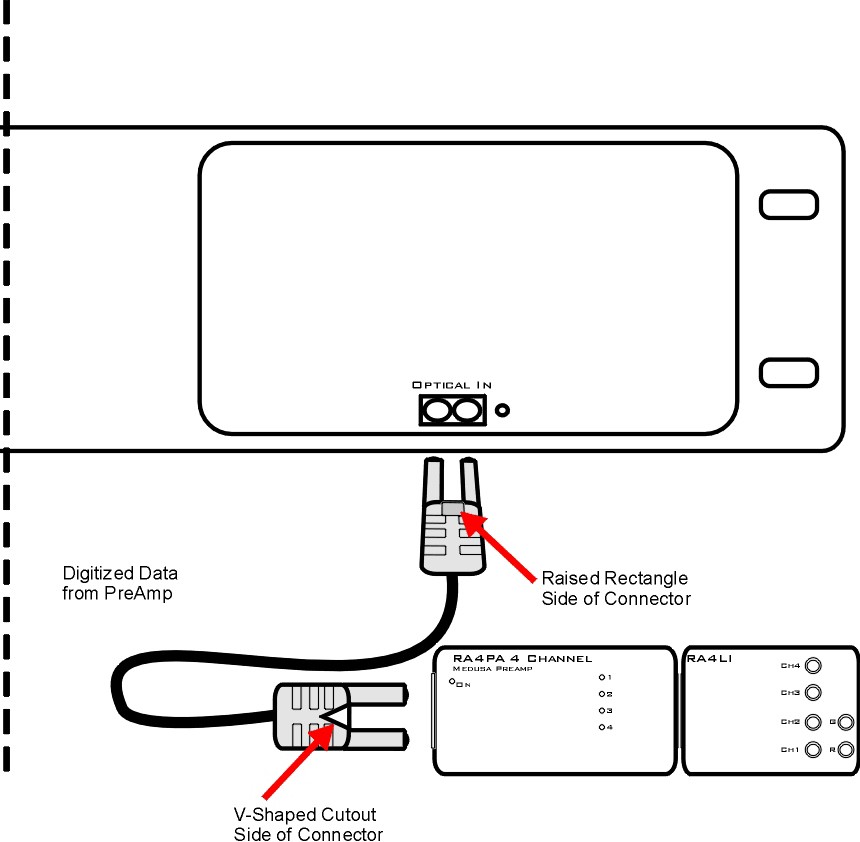
The duplex fiber optic cable has identical one-piece connectors at each end. There is a V-shaped groove on one side of the connector and a raised rectangle on the other. As shown in the image above, plug the connector into the RZ6 port with the raised rectangle side up. Plug the connector into the preamplifier with the V-shaped groove up.
The green LED next to the Optical In port on the RZ6 will illuminate when the preamplifier is connected and both devices are powered on. This indicates that the Medusa4Z is properly time-locked with the RZ6.
Mic Inputs The BNC input connector is used during system calibration. See Calibration.
For more information on the RZ6 and full system specs, see the System 3 Manual.
PC and Interface
The RZ6 must be directly connected to a PC, which provides the user interface for the system. The PO5 or PO5e optical interface card is installed in the PC and connected to the RZ6 across fiber optic cables. This adds another layer of noise reduction, separating the processor from the noisy PC environment.
The PC handles:
-
Configuring the hardware and software.
-
Communicating with the TDT hardware and transferring data across a fiber optic interface.
-
Displaying and working with data during and after acquisition.
If you use TDT's WS4 computer, the optical interface and BioSigRZ software are pre-installed.
If you use your own PC, you'll need to install the interface card and BioSigRZ software yourself. Step-by-step instructions for installing software and drivers and setting up the processor are available in System 3 Installation Guide that came with your system. The installation guide also includes information for connecting the WS4 or your PC to the RZ6 Processor, including running a transfer test to ensure communication between them is working correctly.
Note
A UZ3 (USB 3.0) interface is also available if you wish to use a laptop.