Sound Chamber Fundamentals
Reflections and interference inside of a sound chamber can distort the stimulus frequency or have an undesirable effect on the stimulus level. This section provides supplemental information on these issues and correctly setting-up your sound chamber.
Reflections and Interference
Sound waves are a mechanical force in which pressure is used to transmit energy through a physical medium. Sound waves can be reflected off surfaces. The reflected signal strength is based on the angle of incidence and damping factor of the reflecting surface.
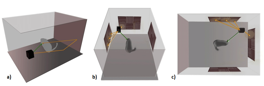 |
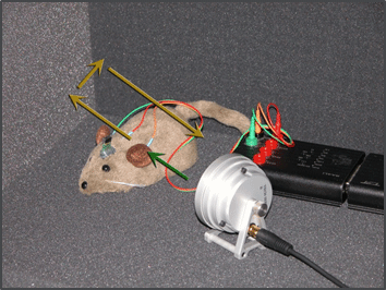
| Figure 1 - Sound wave reflection vectors inside a sound chamber |
Constructive & Destructive Interference
The signal strength at a specific point of interest (e.g subject's ear, calibration microphone location) can increase or decrease depending on the phase delay, frequency, distance of travel and damping factor of the material.
For this reason, the measured dB SPL of a specific frequency may vary greatly depending on the combination of the primary signal and its reflections at the recording site, which may appear as drop outs or spikes in the calibrated frequency response for your speaker.
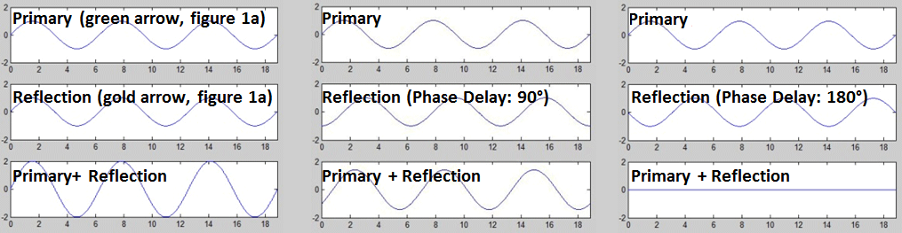 |
| Figure 2 - The summation of signals during constructive interference (left), partial interference (middle), and fully destructive interference (right). The level of interference is based on the frequency-specific phase delay, which is based on wavelength and distance of travel for the primary and reflected signals. |
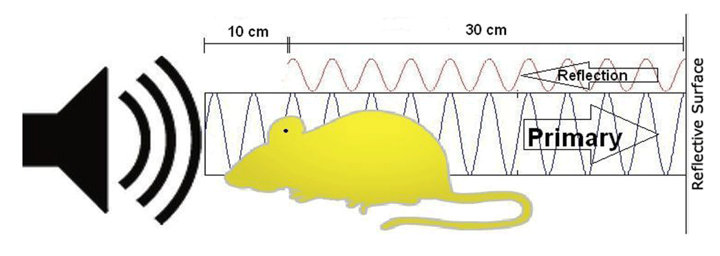 |
| Figure 3 - A standing wave that is present at the subject's ear when the reflection returns |
Constructive and destructive interference is caused by standing waves and their reflections. In the model configuration above, with a speaker-subject distance of 10 cm, a subject-wall distance of 30 cm, and a reflective distance of 70 cm, any stimulus longer than 0.175 ms will generate a temporary standing wave.
The table below shows speaker position offset tolerances with respect to frequency. It further emphasizes how reflections can affect standing waves and tone pips at various frequencies. The ∆ value is the relative distance or tolerance between fully constructive and fully destructive interference. This value represents a 180° phase shift over a reflected distance or λ/4. The speaker-subject spacing and tolerance is very sensitive to change, especially at higher frequencies. If a speaker's position is displaced by a distance of 2.68 mm, for a 32 kHz stimulus, the reflection's phase is shifted 180° and could greatly reduce the perceived intensity.
Ways to Reduce Reflections and Interference
To reduce reflections and interference:
-
Increase the distance of travel for the reflections by changing the angle of incidence. If the angle of incidence is near a corner but not focused directly at a corner, the reflections will bounce off both walls and scatter throughout your chamber rather than bounce off one wall before converging at the center of the chamber.
-
Increase the damping factor by covering hard surfaces (metal, tile, wood, plastic, etc.) with soft, spongy, non-reflective, sound absorbing materials (carpet, foam, etc.).
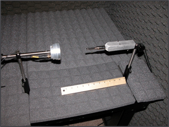
Figure 4 - A sound chamber used for testing and calibrating speakers
The walls and table top in Figure 4 are covered by 1 inch foam pads with 1 inch tall pyramid projections (total thickness of 2 inches) for increased scattering.
Important
The external shell is metallic and tied to earth ground, which doubles as a Faraday cage that will shield against electromagnetic radiation.
 |
| Figure 5 - An example of a good sound chamber |
The floor and walls in Figure 5 are covered in soft, absorbing surfaces (1.75 inch foam padding) with significant damping power. The speaker and subject are aligned slightly off-axis with the wall to maximize scattering.
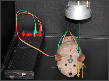 |
| Figure 6 - An example of a bad sound chamber |
The speaker orientation in Figure 6 is an example of poor sound chamber preparation for two reasons. First, the speaker is angled directly at the floor, so the stimulus will be reflected directly back into the subject's ear. Second, the floor is a hard reflective surface that offers little to no damping.
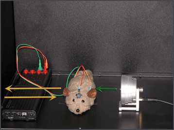 |
| Figure 7 - An example of a bad sound chamber. |
Figure 7 is also incorrect because the speaker is aligned orthogonal to the wall, which also provides a direct reflective path back to the subject's ear. In both cases, depending on the exact distance of travel, the reflections will accumulate at the subject's ear to create constructive or destructive interference, which will distort the stimulus and give an undesired sound pressure level.