Calibration
All speakers have some variation in output across frequencies. When you use a speaker with a known frequency response in BioSigRZ, you can adjust the stimulus output for these known frequency characteristics by selecting your speaker from a list in the Stimulus Setup.
Standard calibration files for common speakers and microphones are provided with BioSigRZ and a speaker-specific custom calibration file might also have been provided with your speaker (provided on a USB drive in the speaker kit). If a calibration file is not provided for your specific speaker model or the distance (free-field experiments) or length of tube (closed-field experiments) is different than those measured for the standard files, you can create a custom file using BioSigRZ's Calibration tools and a calibration microphone.
The first time you run an ABR, we recommend skipping calibration until after you have been able to successfully record an ABR response. If the system has not yet been fully tested, using a custom calibration file can make problems more difficult to diagnose.
How Often to Calibrate
After your system is set-up and working well, how often you calibrate is up to you. Some researchers prefer to calibrate every day, others prefer once a week, monthly or longer. If you are using a robust speaker, like the TDT MF1 magnetic speaker, you may choose to calibrate less often. If you are using a more specialized speaker, like the TDT EC1 or ES1 electrostatic speakers, you may choose to calibrate more often. If you are new to collecting ABR data, consider running a calibration check often enough to confirm that you are seeing less than 5 dB variability, then reducing frequency of calibration to something suitable to your protocol and experiment conditions. We do recommend calibrating anytime your setup (layout or hardware) has changed.
Hardware Setup
To calibrate your system you should have everything set-up as you will have it setup for your experiment, with the exception of the subject. During calibration you will place a calibration microphone with a flat response in the band of interest in the place of the subject. The Amp/BYP switch on the front of the RZ6 must be set in the 'Amp' position, and the Gain knob should be set to 40 dB to start.
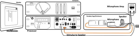 |
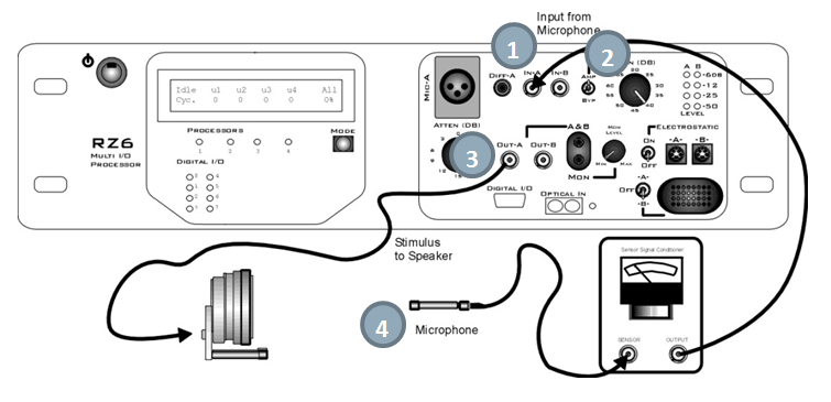
| Free-Field Calibration Setup |
Important
Use only one input for channel A at a time. Attempting to input signals from multiple sources will produce an erroneous signal.
Important
To ensure accurate calibration, give the microphone 10 minutes to warm-up before testing.
Closed Field
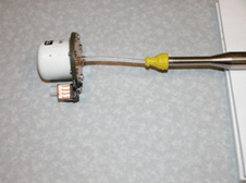
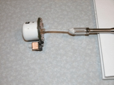
For a closed field calibration you need to interface your Calibration Microphone to your speaker tube using some sort of coupler. Couplers can be made from parts common in most labs (pictured below), such as ear insert adapters, syringes, and putty. All of the connections between the speaker, tube, coupler and microphone need to be airtight. Any gaps, holes or other leaks will cause inaccurate calibrations.
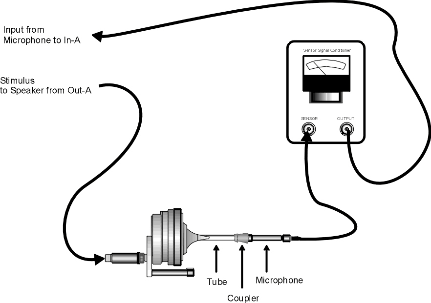 |
| Closed-Field Calibration Setup |
Possible coupler materials:
Tone Calibration
During calibration, BioSigRZ performs a sweep over the frequency range of interest and generates a speaker response curve along with a correction curve that would be required to flatten the response. An FIR filter is calculated from the correction curve and stored in the contents of the calibration file. When you load the calibration file, that filter is loaded onto the RZ6 so that any Tone Pips presented through the RZ6 will be calibrated to have a flat response across all frequencies.
The extension for calibration files is .tcf. All TCF files should be stored at:
C:\TDT\BioSigRZ\TCF
For more information on file types and calibration see the BioSigRZ Manual.
Click Calibration
The RZ6_Click_Calibration.rcx circuit is designed to allow you to
calibrate the RZ6 for click stimuli. This file is part of the
BioSigRZExamples.zip
zipped example folder, which can be downloaded from the TDT website.
Download and extract the zipped files to:
C:\TDT\BioSigRZ\RCX
To use this circuit there are a few steps required for setup:
-
Connect your Calibration Microphone to the In-A port on the RZ6.
-
If your microphone has a sensitivity of less than 50 mV/Pa, ensure your Amp/BYP switch on the front of the RZ6 is set to Amp.
-
Connect your speaker to Out-A or Electrostatic-A (if using Electrostatic-A, be sure the Electrostatic On/Off switch is in the On position).
-
Place your microphone in the same position that your subject's ear would be located.
-
Launch TDT's RPvdsEx software and open
C:\TDT\BioSigRZ\RCX\RZ6_Click_Calibration.rcx -
In the circuit, double-click the ConstF component labeled Microphone Amplification Level and set its value to match the Gain knob on your RZ6. Typically 40-60 dB works well, if your microphone has 1-3 mV/Pa sensitivity. If you are bypassing the amplifier, set the gain in the circuit to 1.
-
In the circuit, modify the ConstF labeled Microphone Calibration Voltage to match the sensitivity of your microphone.
To run the circuit:
-
Click the Compile, Load, and Run button on the tool bar.
-
Start with a low voltage in the Desired Voltage Amplitude ConstF and slowly increase this value. Re-compile, load and run (step 8) after you make any modification to the circuit.
-
When the dBSPL level shown in the top right corner of the screen matches your desired level, make a note of the voltage you are using in the ConstF labeled Desired Voltage Amplitude.
-
This voltage and the corresponding dB level should be entered in the click signal stimulus configuration file found at:
C:\TDT\BioSigRZ\SIG\Click.sig-
To open the SigGenRZ stimulus design software (included with BioSigRZ), click the Windows Start menu, click All Programs, click TDT Sys3, click SigGen Solutions, and then click SigGenRZ.
This program can be used to edit stimulus files.
-
To open the standard click stimulus file, click File, click Open, browse to:
C:\TDT\BioSigRZ\SIG\Click.sigThen click Open.
-
On the main toolbar, click Modify, and then click Signal.
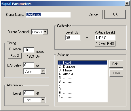
-
In the Signal Parameters dialog box, enter the voltage and the corresponding dB level in the Calibration area, and then click OK.
-
-
To save the change, click File then Save.
This will save the change to the stimulus used by BioSigRZ's standard click configuration.
-
Run the stimulus file in BioSigRZ without a calibration (.tcf) file applied to the stimulus. Your stimulus is already calibrated, and adding a .tcf file will cause the calibration to be incorrect.
See the System 3 Hardware Manual for detailed information on TDT equipment and see the BioSigRZ Manual for computer requirements and detailed software reference.
Testing Speakers and Microphones
A simple RPvdsEx test circuit can be used to ensure your speakers and
microphones are working. The test circuit, SpeakerMicTest.rcx, is part
of the BioSigRZExamples.zip
zipped example folder, which can be downloaded from the TDT website.
Speaker Test
If you suspect that your speakers may not be functioning correctly, download and extract the zipped files to:
C:\TDT\BioSigRZ\RCX
Then double-click the SpeakerMicTest.rcx file to launch RPvdsEx and open the file.
To use this circuit there are a few steps required for setup:
-
Connect your speaker to Out-A.
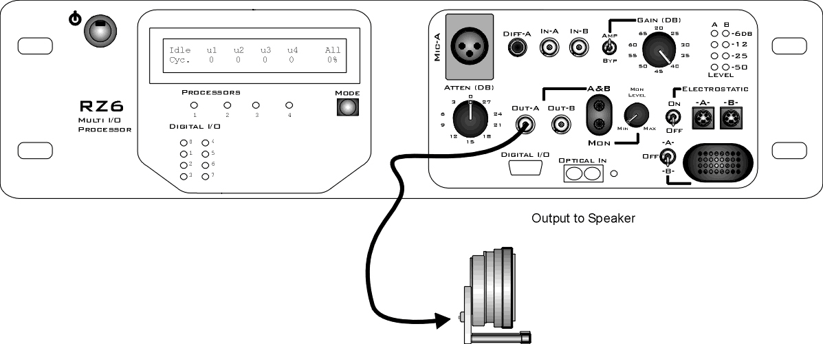
RZ6 with MF1 Speaker
To test your speaker:

Click the Compile, Load, Run button on the toolbar. You should be able to hear a tone from the speaker.

Click the Stop button to stop the test.
Microphone Test
After you've confirmed at least one speaker is working, connect the calibration microphone and run the circuit again.
Important
To ensure accurate calibration, give the microphone 10 minutes to warm-up before testing.
To use this circuit there are a few steps required for setup:
-
Connect your Calibration Microphone to the In-A port on the RZ6.
-
If your microphone has a sensitivity of less than 50 mV/Pa, ensure your Amp/BYP switch on the front of the RZ6 is set to Amp.
-
Place your microphone where your subject's ear would be located.
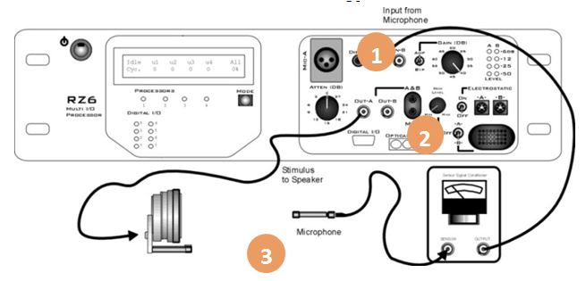
RZ6 Open Field Calibration Setup 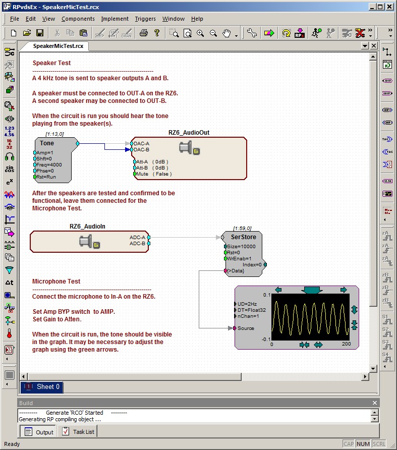
You should be able to see a sine wave in the graph. You may need to adjust the scale using the green arrows on the sides of the graph. Click the Stop button again to stop the test.